


Learning Resources > Tutorials > Getting Started with Maya > Polygon Texturing > Lesson 1: UV texture mapping >
Working with UVs in the UV
Texture Editor
When texture mapping a polygon or subdivision surface type model it is often necessary to modify the UV components for a model so they match the texture map. The UV Texture Editor provides many tools for working with UVs. In this section you learn how to:
You can select UV components from either the scene view or within the UV Texture Editor. Displaying both the 3D scene view and the 2D view of the UV Texture Editor lets you easily correlate which UV components are associated with a particular edge or vertex on the 3D model.
This is very helpful to understand the layout and orientation of your UV texture coordinates in relation to the image used for a texture map and how the map appears on the model in the 3D scene view.
To select UVs for a 3D model in the scene view
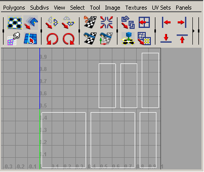
Display Image works by turning the display of the assigned texture on or off in the 2D view of the UV Texture Editor. Turning the image off temporarily aids in viewing only the UV components. This will be useful in the steps that follow.
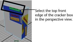
Selecting a UV is very similar to selecting a vertex on an object. That is, you select a point that resides in exactly the same position as the vertex. When you select a UV in the scene view, the corresponding UV is also selected in the UV Texture Editor.
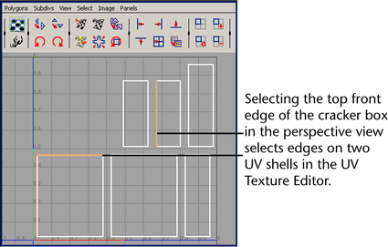
When you select this edge in the scene view, notice that two corresponding shell edges also get selected in the UV Texture Editor. This indicates the following:
This is useful when you need to understand how the various UV shells relate to each other, especially when you have many UV shells for a model in the scene; for example, when you sew two UV shell edges together.
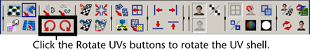
In the steps that follow you select edges in the UV Texture Editor so you can sew them together.
Sewing UV shells together merges the UV shells along a shared edge that you specify. Sewing UVs is useful for the following reasons:
To sew shell edges together in the UV Texture Editor
When the top front edge is selected in the scene view, the top edge of one of the large UV shells is also selected as well as the left side of the middle UV shell in the top row of the UV Texture Editor. For the cracker box texture map, you need to sew these together so they correlate to the map correctly.
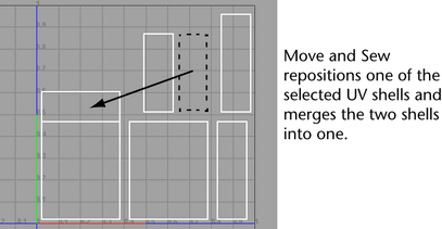
The small rectangular UV shell is repositioned to match the top of the large UV shell and the two shells are combined into one. When you later select and move this sewn shell, it will move as one piece. When two UV shells are selected for sewing, the smallest UV shell is moved to the larger.
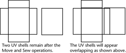
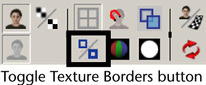
In the UV Texture Editor, the texture borders for two UV shells now appear with a thicker line.
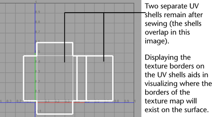
Displaying texture borders on the UV shells is useful for visualizing where the texture borders exist on the 3D model in the scene view. That is, any portion of the texture image that appears outside of the texture border will not appear on the surface. It is particularly useful for troubleshooting texture mismatches when they occur. Displaying the texture borders can also help to identify which UV shells are combined and which shells are not when you have many UV shells displayed in the UV Texture Editor.
If you want to be able to view areas where UV shells overlap in the UV Texture Editor select Image > Shade UVs. When Shade UVs is turned on any selected UV shells appear shaded in a semitransparent fashion. Areas where the shading appears more opaque indicate the regions of shell overlap.
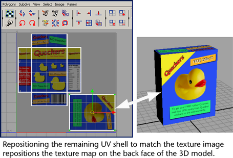
In the steps that follow, you reposition the two UV shells in the UV Texture Editor so they coincide with the texture image.
You manually reposition UV components in the UV Texture Editor using the tools within the Toolbox. To reposition an individual UV component you must first select it before selecting the Move Tool. To reposition an entire UV shell you must first select one individual UV from the shell it belongs to and then convert the selection to a shell before using the Move Tool.
To move UVs in the UV Texture Editor
The texture image displays in the 2D view of the UV Texture Editor dimmed, as before. You need the image displayed so you can accurately reposition the two UV shells. Dimming the image aids in seeing the selected UVs.
The selection changes from a single selected UV to selecting the entire UV shell.
 .
.
The Move Tool manipulator icon appears over the selected UV shell.
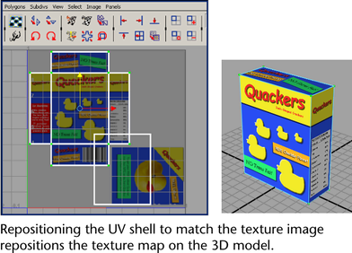
The position of the texture updates on the cracker box model in the scene view as you do this.
The selection changes from a single selected UV to selecting the entire UV shell.
The texture map should now appear correct on all sides of the cracker box when you’re finished.
If you need to move a single UV so it precisely matches a particular location on the texture map you can turn on Pixel Snap (Image > Pixel Snap). When you select and move the UV using the Move Tool, it will reposition the UV coordinate based on pixel boundaries.