Learning Resources > Tutorials > Getting Started with Maya > Polygon Texturing > Lesson 1: UV texture mapping >
Mapping UV texture coordinates
It is often necessary to create new UVs for a surface mesh in order to texture map it correctly. These situations include:
This can occur when you import 3D models from other software applications that don’t create UVs.
This can occur when a surface has been edited or modified in some way and it becomes hard to determine what UVs may be missing as a result.
For example, if you want to paint a texture map directly onto a 3D surface, you may want to map UVs that allow you to paint using the 3D paint tools in Maya. Alternatively, you may want to create a unique set of UVs specifically for baking textures or light maps.
Maya lets you create UVs for polygonal and subdivision surfaces using a process called projection mapping, also referred to as mapping UVs. Maya provides several projection mapping types that map what gets viewed by a particular projection to a flat 2D view that can be subsequently correlated to your texture map using the UV Texture Editor.
In this lesson, you use a feature called Automatic Mapping to create new UVs for the cracker box model. Automatic mapping lets you specify the number of planes that will be used for the UV projection.
Automatic Mapping is normally used when mapping UVs that require multiple projections of organic shaped models as it has the advantage of producing UVs that are proportional in scale to the world space area of the mesh faces of the surface.
Automatic mapping is useful when your mapping requirements are for non-overlapping UVs which fit within the 0 to 1 texture space, but which do not have to be contiguous; for example, when using the 3D Paint tool, Maya® Paint EffectsTM, Maya® FurTM or Maya® HairTM.
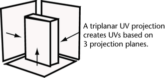
You use Automatic Mapping in this lesson because it can produce a UV projection from three planar directions simultaneously which makes it a good choice for the shape of the cracker box model. That is, you can map UVs for the front and back, top and bottom and the two sides in one operation. This projection type is referred to as a triplanar projection.
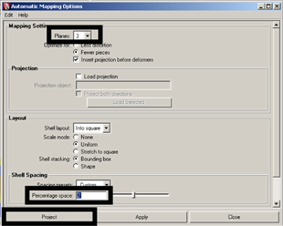
To map UVs using Automatic Mapping
 .
.
Setting Planes to 3 creates UVs based on projections from three separate directions. Setting the Percentage Space option to 2 sets the size of the space that appears between each of the separate UV projections when they are laid out in the UV Texture Editor.
When the projection is complete the new projected UVs from the triplanar projection appear in the UV Texture Editor.
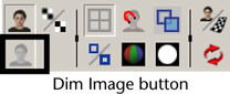
The intensity of the image map is reduced so you can view the UV borders on the projected UVs more easily. The new UVs appear in the UV Texture Editor as shown below.
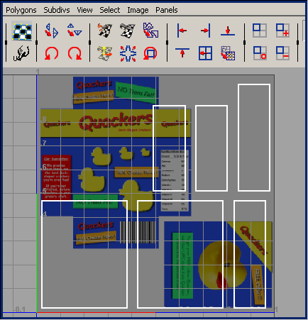
The texture map still does not appear correctly on the cracker box because the UV shells need to be repositioned so they align with the corresponding components of the image map.
While the shape of each UV shell is now recognizable as being associated with the cracker box, it is not apparent which components in the UV Texture Editor correspond to a particular face on the cracker box.
In the next section you learn how to select and reposition the UV shells so they better match the image for the texture map.