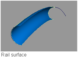
Creates a surface by sweeping one or more profile curves along one or two rail curves.
To sweep a curve along one or two paths
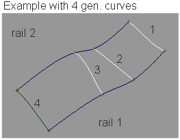
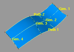
Create a surface by sweeping or blending one or more generation curves along one or two path curves (rails).
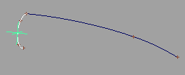
The Rail Surface tool takes its name from its use of one or two “rail” curves. The generation curves maintain contact with the rails at the same points through the sweep, like a train traveling on a track.
The Rail Surface tool is similar to the Extrude tool, but has many more options and much more power.
The appearance of the Rail Surface icon depends on the Generation Curves and Rail Curves settings in the Rail Surface Options window.
To sweep one generation curve along one rail curve
The procedure for using the Rail Surface tool has several optional steps, depending on the settings in the Rail Surface Control window.
 icon, or choose Surfaces > Swept Surfaces > Rail Surface❒ from the tool palette.
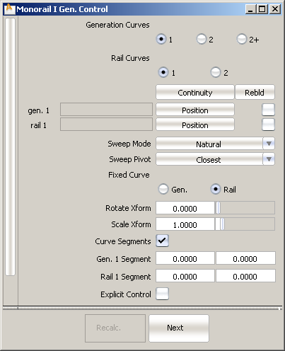
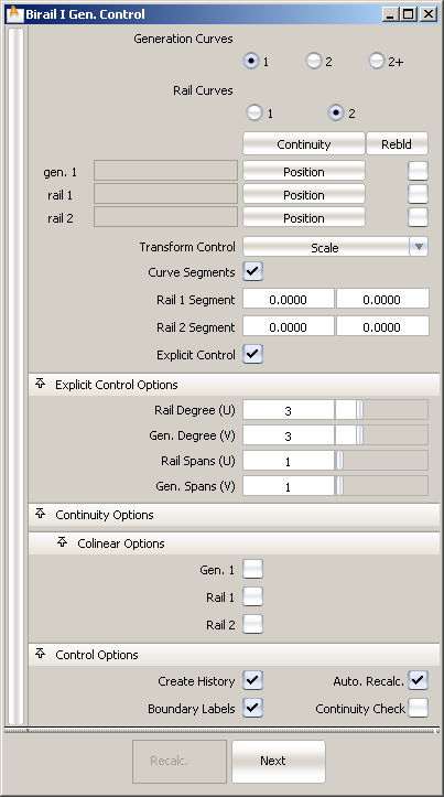
The Rail Surface Control window appears.
You almost always want construction history on. This allows you to change the settings after you sweep the curves.
This example uses the following settings.
When you are satisfied with the new surface, you can delete the history information with Delete > Delete Construction History .
.
The generation curve can be a free curve, isopam curve, curve on surface, or trim edge.
The rail curve can be a free curve, isoparametric curve, curve on surface, or trim edge.
To sweep one or more generation curves along two rail curves
icon, or choose Surfaces > Swept Surfaces > Rail Surface ❒ from the tool palette.
The Rail Surface Control window appears.
You almost always want construction history on. This allows you to change the settings after you sweep the curves.
When you are satisfied with the new surface, you can delete the history information with Delete > Delete Construction History.
Set Generation Curves to the number of generation curves to use:
The generation curve(s) can be a free curve, isoparametric curve, curve on surface, or trim edge.
If Generation Curves is 2+, pick all the generation curves in order, then click Go.
The generation curve(s) must intersect both rail curves.
The rail curves can be free curves, isoparametric curves, curves on surface, or trim edges.
 icon, or choose Surfaces > Swept Surfaces > Rail Surface ❒ from the tool palette.
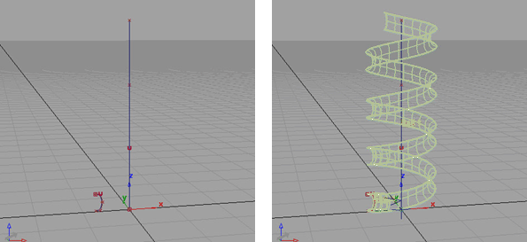
The generation curve’s pivot point moves along the rail curve. Since the pivot is offset from the actual generation curve, the generation curve sweeps the new surface at an offset from the rail curve.
For example, if you enter 360, the generation curve makes one full revolution as it travels the length of the rail curve.
helix curves helix curves active
 icon, or choose Surfaces > Swept Surfaces > Rail Surface ❒ from the tool palette.
For example, if you enter 2, the generation curve grows twice as large as it travels the length of the rail curve. If you enter 0.5, it shrinks by half.
To edit the construction history of a Rail surface
icon, or choose Surfaces > Swept Surfaces > Rail Surface from the tool palette.
The Rail Surface Control window appears.
Turn on the Rebuild option for all rail curves to remove multi-knots and set the weight of all CVs to 1 before creating the surface.
For example, if you turn on the Curve Segments option after you have already picked the generation curve, you will not be asked to define curve segments. However, after the surface is built, text boxes will appear in the Rail Surface Control window where you can change the start and end parameters for the curve segments. You can also click the Next button and start again.
To change the Curve Fit Distance option, choose Construction Options from the Preferences menu.
In these cases, try reversing the choice of generation and rail curves, and choose the shorter, simpler curves for the generation curves and long, winding curves as the rails.
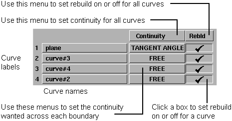
The Continuity Table displays one row for each boundary curve involved in the rail operation.
For example, before creating the surface, rebuild the first rail curve, second rail curve, first generation curve, and/or last generation curve. (To rebuild interior generation curves, use the Rebuild Interior Gen. Curves option below.)
This can improve the parameterization and reduce the complexity of the new surface when the curves are complex.
Rebuilding curves can also remove multi-knots and reset the weight of all CVs in the rail curve(s) to 1. This is necessary for rail curves with multi-knots or CV weights.
Position – Only keep positional continuity. This is the default.
Implied Tangent – Try to keep tangency with an implied surface that shares this edge. The implied surface is the surface that would be created by mirroring the new surface.
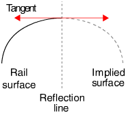
Implied Curvature – Try to keep curvature continuity with an implied surface that shares this edge. The implied surface is the surface that would be created by mirroring the new surface.
Implied Tangent and Implied Curvature are powerful features. They let you model one half of a symmetrical surface (such as a car body), and maintain continuity at the seam. When you duplicate the surface to create the other half, the seam will already be continuous.
For this to work across a symmetry plane, you must make sure the ends of the curves are tangent or curvature continuous across the symmetry plane. (For tangency, this means the tangents are perpendicular to the symmetry plane).
Tangent Angle – Try to keep tangency at an angle with a surface that shares this edge.
The Rail Surface tool calculates the tangent angle at both ends of the common edge. If the two angles are different, Rail Surface blends between them to determine the angle to keep at every point along the edge.
A tangent angle of 0.0 (or 180, -180, 360) is equivalent to Tangent continuity.
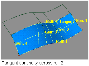
Tangent – Try to keep tangency with a surface that shares this edge.
Curvature – Try to keep curvature continuity with a surface that shares this edge.
Proportional – Rebuild the rail curves to create a surface with proportionally spaced spans and smooth parameterization based on the first rail curve.
This option is only available when Rail Curves is 2 and at least one rail curve is being rebuilt.
Natural – As the generation curve sweeps along the rail, it pivots to maintain the same angle relative to the rail curve.
This option is only available when Rail Curves is 1. It has the same effect as the Tube option in the Extrude tool..
Parallel – As the generation curve sweeps along the rail, it maintains its original orientation.
This option is only available when Rail Curves is 1. It has the same effect as the Flat option in the Extrude tool.
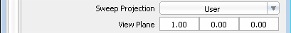
View – As the generation curve sweeps along the rail, it only rotates in one plane (choose the plane with the Sweep Projection pop-up menu). This maintains the visual angle between the generation and rail curves.
Spine – Use a spine curve to control the orientation of the generation curve as it sweeps along the rail.
This option controls the plane in which the generation curve is allowed to rotate when the Sweep Mode is View.
This option appears when Sweep Mode is View.
Active – Take the rotation plane from the current view window.
XY XZ YZ – Use a global plane (XY, XZ, or YZ) as the rotation plane.
User – Type a 3D vector in the View Plane text boxes to define a plane.
This option is only available when Rail Curves is 1.
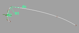
Sweeping involves two pivot points:
You can have Rail Surface set the pivot points automatically (as in Extrude), or set them manually for the generation and rail curves.
Closest – Set the pivots to the closest points on the two curves.
This option is the default. It works best when the generation curve is close to the start or end points of the rail curve.
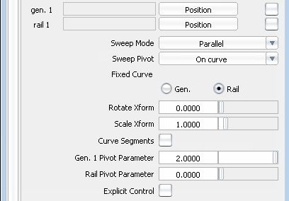
On Curve – Set the pivots to specific parameters on the two curves.
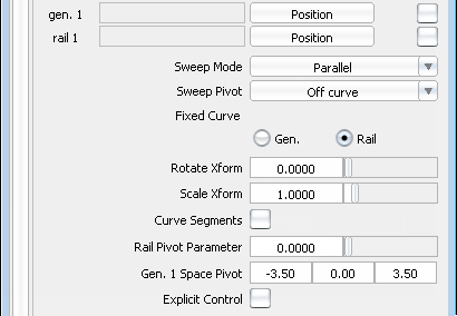
Off Curve – Set the pivots to a specific parameter on the rail curve and a 3D point in space for the generation curve.
This option controls how the Rail Surface tool modifies the generation curves to stay on the rail curves during the sweep. It is only available when Rail Curves is 2.
Scale – Scale the generation curve proportionally, to the size necessary for the curve to stay on both rails.
Non-Prop Scale – Scale the generation curve non-proportionally, along the vector connecting the rail curves.
Rotate & Trim – Rotate the generation curve around the intersection with the first rail curve, so that the generation curve stays on both rails. Trim away any part of the new surface that goes beyond either rail curve. The generation curve is not scaled.
This option only applies when Generation Curves is 1.
Rotate No Trim – Rotate the generation curve around the intersection with the first rail curve, so that the generation curve stays on both rails. The generation curve is not scaled.
This option only applies when Generation Curves is 1.
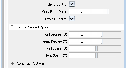
Blend Control – Enable the Gen. Blend Value slider to control the midpoint of the blend between the two generation curves.
This option appears when Generation Curves is 2.
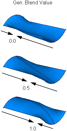
Gen. Blend Value – The percentage of the distance (from 0 to 1) along the rails where the influence of both generation curves is equal.
For example, a value of 0.5 (the default) blends the two curves equally, so that the halfway point of the blend occurs at the midpoint of the rails.
A value of 0.25 places the halfway point of the blend 25% of the distance along the rail curves, hence giving more influence to the second generation curve. Conversely, a value of 0.75 would give more influence to the first generation curve.
The values 0.0 and 1.0 still blend the two curves a minimum amount.
This option determines which of the curves will be moved in order to make the two pivot points coincide before the sweep. This in turn controls where the new surface will be created.
This option is only available when Rail Curves and Generation Curves are both 1.
GEN. – Keep the generation curve fixed and move the rail. The new surface is built beginning at the generation curve.
RAIL – Keep the rail fixed and move the generation curve. The new surface is built along the rail curve.
Available only when Rail Curves and Generation Curves are both 1.
The degree of rotation as the generation curve sweeps along the rail curve.
For example, if Rotate Transform is 45, the generation curve will rotate 45 degrees as it sweeps along the length of the rail curve. Use negative numbers to rotate in the opposite direction.
Available only when Rail Curves and Generation Curves are both 1.
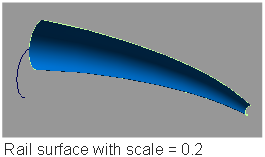
The scale factor as the generation curve sweeps along the rail curve.
For example, if Scale Transform is 2, the generation curve will double in size as it sweeps along the length of the rail curve. If Scale Transform is 0.5, the generation curve will shrink by half as it sweeps.
This option only applies when Generation Curves is 1.
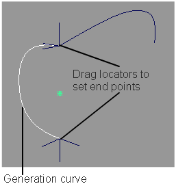
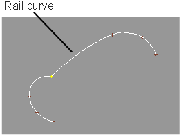
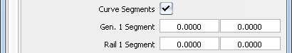
Specify sections of the generation and rail curves to use in the sweep.
When this option is on, you will be prompted during the sweep procedure to click start and end edit points on the first rail curve and possibly (depending on the other settings) on the second rail and/or the generation curve.
After the surface is built:
or
Specify the maximum number of spans that can be added to the surface (in both the U and V direction) when attempting to maintain the requested levels of continuity.
If this number is too small, continuity may fail along some of the edges.
Max. New Spans is not available when Explicit Control is turned on.
On – Insert extra edit points at the midpoint of the span with the largest continuity deviation. This is the default, and results in a better distribution of the isoparametric curves.
Off – Insert extra edit points at the location of the largest continuity deviation.
Insert at Midpoint is not available when Explicit Control is turned on.
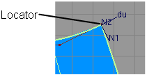
Display the surface continuity locator at the boundaries between the rail surface and adjacent surfaces. The locator is persistent
and will remain after you exit from the Rail Surface tool. To remove it, use Pick > Locator to pick the locator, then select Delete > Delete Active
 , or toggle the checkmark off when entering Rail Surface tool again.