Use the twist rig to twist a surface or collection of surfaces about a single axis curve.
To twist a collection of surfaces
 from the tool palette.
The target geometry is accepted and highlighted in pale green.
The twist axis curve can be a free curve, a surface boundary or isoparametric curve (isoparm), a trim curve, a curve-on-surface, or a part of a trim-mesh (isoparms that have been truncated by trimming). You can even use curves that are created by increasing patch precision. The tool prevents you from using a curve that is related to any target surfaces. If you have a curve on a target surface that you would like to use as a twist axis, you must duplicate the curve first.
After you have applied the Twist Rig, you will see something like the following screen shot (In this example the target is an elongated cube):
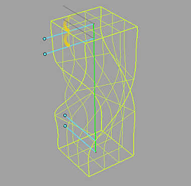
Initially, the Twist Rig inserts four Twist Handles along various points of the axis.
Also, notice that the Twist Rig has highlighted the axis curve in bright green.
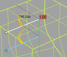
Twist handles are visual representations of the Twist Profile, a set of value pairs showing the position and angle of twist, called the Twist Angle. A twist profile can have one or more twist angles. If there is a single twist angle, the twist is equivalent to a rotation about the twist axis.
When a twist handle is selected, it turns white. The angle and position represented by the handle are displayed numerically, as shown in the next image. T90.000 is the angle of rotation for the twist handle, and 0.90 within the red box is the relative position of the handle along the axis curve, which is parameterized from 0 through 1.
For selected twist angles, you can:

When targets are added to the rig, they are duplicated. The shape modifications are performed with these duplicated geometry. To restore the original geometry and to delete the modified geometry and history, click Revert. Notice that the manipulated modifiers do not return to their status before the dynamic modeling.
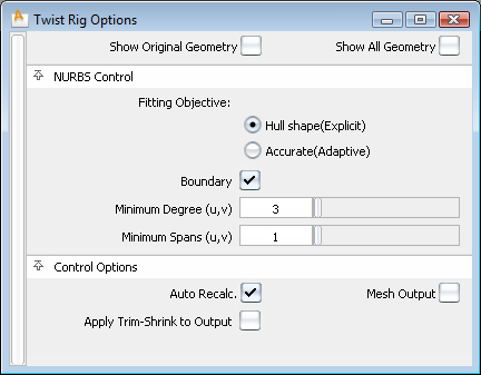
If checked, this box enables the display of geometry as it was before the Twist Rig tool was applied. If unchecked, the current version of modified geometry is displayed. Use this feature to flip and compare “before” and “after” geometry.
If checked, this box enables the display of both the original and modified geometry.
The fields in this section control the way the Twist Rig tool modifies NURBS target surfaces. Settings in this window have no effect on meshes that were selected as targets. If all targets are meshes, or if Mesh Output is set, this section of the option window is hidden.
Specifies the minimum degree of resulting patches. If a patch target has degree less than the specified degree, its degree is raised to the specified degree. This has the result of making the math heavier, but in general the results of the shape modification are more accurate.
Specifies the minimum number of spans in the U and V directions. If necessary, existing spans are subdivided. This has the result of making the math heavier, but in general the results of the shape deformation are more accurate.
The controls in this section can be used to adjust the output geometry.
If checked, any changes in any field in the control box or to the twist profile lead to an automatic update of the model display. If Auto Recalc is not checked, click the Go button in the active window to update the display after any changes. Normally, if you have a very large model that takes a long time to update, you should leave the Auto Recalc box unchecked. Auto Recalc is checked on by default.

If Auto Recalc. is ON, the Go button is not shown. Any changes to the rig (options or constructors) causes the history to re-evaluate.
If Auto Recalc. is OFF, the Go button is displayed. Any changes to the rig cause the Go button to be enabled, and when you click Go the re-evaluation occurs. History itself exists the moment you enter the tool — not clicking the Go button does not change this, and you do not lose history by prematurely leaving the tool.
If checked, NURBS are tessellated and output as mesh surfaces.
When checked, the associated output surfaces are trim-shrunk before any shape change. This option changes only the output surfaces, not the inputs. You may find a performance improvement and better results using this option.
What you can do outside the tool afterwards
If you are outside the tool after the twist rig history is set up, you can modify the twist axis curve in any way you normally would in Alias, and the twisted targets will update because of history. For example, you can translate the axis curve and create an off-centered twist. You can also modify the input target geometry, and the twisted targets update as well.


 -clicking) this tool opens the option box.


