


Alias provides a box-shaped manipulator called a lattice to enable global modifications to the model.
The lattice box always starts in disengaged mode, and is initialized as a bounding box enclosing the selected geometry.
The lattice can be modified and refined from its initial box shape without affecting the underlying targets (surfaces or meshes) as long as the lattice is disengaged. After developing a lattice that provides the shape and detail required, engage the lattice. Subsequent changes to the lattice will modify the targets.
The lattice can be repeatedly engaged and disengaged for cumulative shaping modifications.
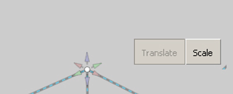
The points on the lattice are not CVs — they are manipulator handles. They can be moved by using only the functions offered by the lattice rig tool.
If there is an active construction plane, a new lattice respects the construction plane and aligns to it. Also, the manipulators of the lattice points independently respect the construction plane. That means that, no matter where or how the lattice is created, the manipulators respect the current active construction plane.
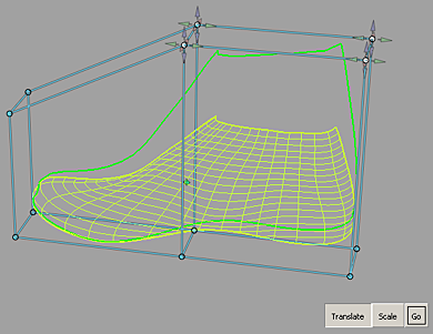
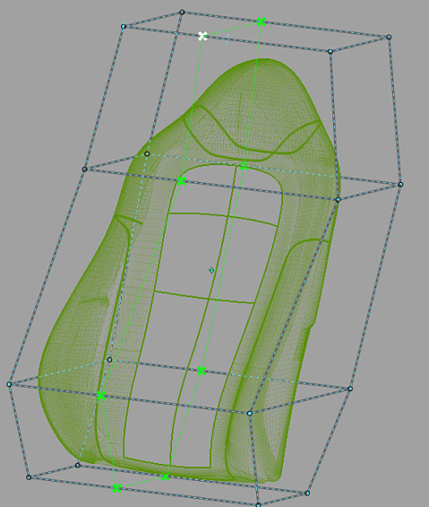
The geometry being modified is represented by a proxy. A proxy is a lightweight wireframe representation of the targets being deformed by an engaged lattice. The proxy interactively updates while you modify the engaged lattice to show what the targets look like after deformation (see the following image). Meanwhile, the targets remain unchanged until you release the mouse button (when auto-recalc option is ON) or when you click GO (when auto-recalc is OFF).
For background information, see Dynamic shape modeling.
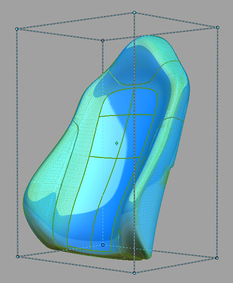
All modifications made to the engaged lattice influence the shape of the targets enclosed by the lattice.
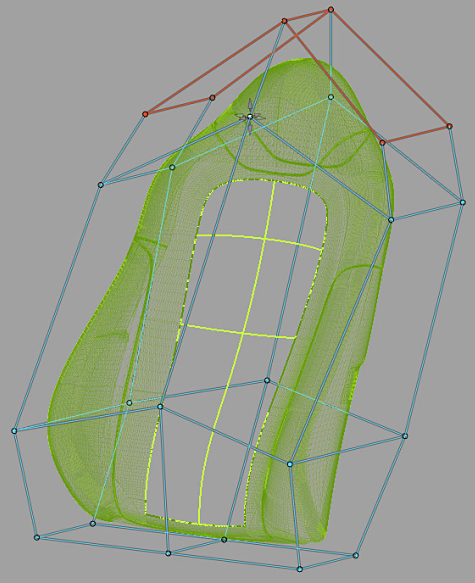
All the geometry not enclosed by the lattice are constrained. To show that these areas have been constrained, the lattice points and edges that intersect the geometry are shown in red.


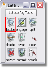
To open the option window, double-click or  -click the icon. For descriptions of the options, see Lattice Rig option window.

The split tool adds new lattice segments like a belt wrapped around the lattice box. The split tool is only accessible while in disengaged mode. To split an edge of the lattice, click this tool, and then click the edge that you want to split. The split is perpendicular to the edge you have selected.
To split the lattice right in the middle between two lattice points, press  (Windows) or
  (Mac) while dragging the new split along the lattice. To confirm the location of the split, click Accept Split. When you have finished splitting the box, click the DONE button.

When targets are added to the rig, they are duplicated. The shape modifications are performed with these duplicated geometry. To restore the original geometry and to delete the modified geometry and history, click Revert. Notice that the manipulated modifiers do not return to their status before the dynamic modeling.
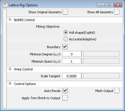
The fields in this section control the way the Lattice Rig tool modifies the NURBS target surfaces. Settings in this window have no effect on meshes that were selected as targets. If all targets are meshes, or if Mesh Output is set, this section of the option window is hidden.
The available methods are:
Hull Shape (Explicit) – Optimizes fitting for hull shape. This option allows for explicit control of minimum degree and spans. If the Boundary field is checked, the fitting is optimized for patch boundaries.
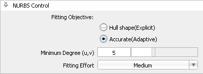
Accurate (Adaptive) – Optimizes fitting for accuracy. This determines the minimum number of spans necessary for an accurate representation of the modified shape.
The Fitting Effort option has been reorganized to a pull-down menu with Low, Medium, High, and Custom values. If Custom is selected, a slider can be used to set the value precisely.
The controls in this section can be used to adjust how the modifier and the constraints influence the target geometry.
If checked, any changes in any field in the control box lead to an automatic update of the model display. If Auto Recalc is not checked, click the Go button in the active window to update the display after any changes. Normally, if you have a very large model that takes a long time to update, you should leave the Auto Recalc box unchecked. Auto Recalc is checked on by default.

If Auto Recalc. is ON, the Go button is not shown. Any changes to the rig (options or constructors) causes the history to re-evaluate.
If Auto Recalc. is OFF, the Go button is displayed. Any changes to the rig cause the Go button to be enabled, and when you click Go the re-evaluation occurs. History itself exists the moment you enter the tool — not clicking the Go button does not change this, and you do not lose history by prematurely leaving the tool.


