Use this tool to bend selected geometry to conform to a user-created curve; or a continuous sequence of curves.
To bend an object or group of objects
 from the tool palette. The target geometry is accepted and highlighted in pale green.
The types of curves that can define a bend axis curve are:
You can even use curves that are created by increasing patch precision.
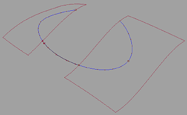
Furthermore, you can use a sequence of curves that are continuous to define a single bend axis. The only requirement is that the curves form a sequence: each curve in the sequence should be positionally continuous to the previous one and the next one in the sequence. The curves need not be of the same type. As an example, the following image shows the combination of curves-on-surface and a free curve together to form a valid bend axis.
After the targets have been selected, the tool examines the bounding box of the targets to see which (X, Y, or Z) axis will be used to map to the bend axis. Typically, the longest axis of the bounding box is used. Also, we refer to the midpoint of the bottom face of the bounding box as the contact point. The contact point is the point-of-reference when you change the placement of the bent target with respect to the bend axis.
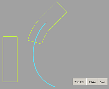
In the Bend Rig, you see something like the following screen shot. (In this example the target is a cube elongated along the z-axis direction, shown inside the tool with a pale green highlight, and the bend axis is a free curve with a cyan highlight):

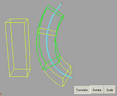
Notice that by default, the Bend rig preserves the size and length of your targets. In this example, the bend axis is longer than the length of the target, so the bent cube only takes up part of the bend axis in the middle.
Inside the Bend Rig tool, you can adjust how the targets are mapped to the bend axis.
Using the GO buttons at the bottom of the modeling window, you can choose to be in translate, rotate, or scale mode.
In Translate mode, you can translate the bent targets along the bend axis. The translation is defined at the contact point, which can be positioned at any point along the curve. In the Bend rig, the contact point is defined as the midpoint of the target.
If there are parts of the target that extend beyond one or both ends of the bend axis, the tool extrapolates tangentially with respect to the bend axis.
To translate, click the Translate button and click-drag along the bend axis — the target follows. While dragging, a bright green outline can be seen (the proxy, which is a lightweight approximation of your target). The proxy allows for real-time interactive update. The targets update for real when you release the mouse button. You can also type in the translation in the current linear working units in either REL (relative) or ABS (absolute) mode. This is the absolute position of the contact point of the target on the curve.
In rotate mode, rotate the target about the bend axis. Click-drag any mouse button to the left or right to adjust the angle. You can also type in the angle in relative (REL) or absolute (ABS) forms.
In scale mode, you can adjust the size of the targets relative to the bend axis. Again, if you managed to scale your target such that it extends beyond the bend axis, the tool extrapolates tangentially. If you use the left mouse button to scale (click-drag left or right), you scale the targets proportionally. If you use the middle mouse you scale only along the curve direction (making the target longer or shorter) and with the right mouse you can scale how “fat” the targets are.
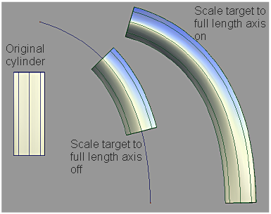
Related to the scale mode is the option to Scale target to full axis length. If this option is on, the target is non-proportionally scaled so that its length matches that of the axis, while its girth is untouched.
You can also change which initial axis along the middle of the bounding box of targets are used for the mapping. Using the Axis Line tool you can choose the X, Y, or Z axis through the middle of the bounding box of the input targets.
If you used as a bend curve a curve related to a surface, the Respect surface normal option may be of interest. When this option is On, in addition to the target following the shape of the curve after the tool is executed, the target also is twisted so that it follows the surface normals that are found along the specified bend axis. This option is not applicable if the bend axis is a free curve — an arbitrary orientation frame is chosen to minimize twisting of the target along the bend axis. If the option is off when using a surface-related curve as a bend axis, the tool treats the surface curve the same as a free curve.

If the bend axis is a mixed-type, continuous sequence of curves, turning on the Respect surface normal option causes the targets to twist such that it interpolates the different surface normals in the sequence of curves in the axis, as shown here:
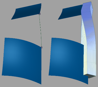
On the left, you can see that original set-up for the bend axis — two surface boundaries with a blend curve between. The two surfaces have very different normal directions. On the right, you see that an elongated cube bent onto this axis twists to accommodate the surface normal direction when the Respect surface normal option is turned on.

When targets are added to the rig, they are duplicated. The shape modifications are performed with these duplicated geometry. To restore the original geometry and to delete the modified geometry and history, click Revert. Notice that the manipulated modifiers do not return to their status before the dynamic modeling.
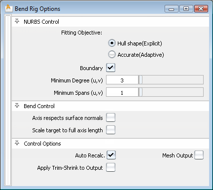
The fields in this section control the way the Bend Rig tool modifies NURBS target surfaces. Settings in this window have no effect on meshes that were selected as targets. If all targets are meshes, or if Mesh Output is set, this section of the option window is hidden.
The controls in this section can be used to adjust the output geometry.
If checked, any changes in any field in the control box or any modifiable parameters (translate, rotate, or scale) lead to an automatic update of the model display. If Auto Recalc is not checked, click the Go button in the active window to update the display after any changes. Normally, if you have a very large model that takes a long time to update, you should leave the Auto Recalc box unchecked. Auto Recalc is checked on by default.

If Auto Recalc. is ON, the Go button is not shown. Any changes to the rig (options or constructors) causes the history to re-evaluate.
If Auto Recalc. is OFF, the Go button is displayed. Any changes to the rig cause the Go button to be enabled, and when you click Go the re-evaluation occurs. History itself exists the moment you enter the tool — not clicking the Go button does not change this, and you do not lose history by prematurely leaving the tool.
What you can do outside the tool afterwards:
If you are outside the tool after bend rig history is set up, you can modify the bend axis in any way, and the bent targets will update because of history. You can also modify the input target geometry and the bent targets update as well.
Commit and Revert tools work the same as they do in the Transformer Rig and Lattice Rig.


