Opens the diagnostic shading control window, which allows you to shade the model using various modes.
Controls how accurately surfaces are tessellated when Tessellator is Fast. The slider range is 0.0001 to 1.0. The default value is 0.1.
The same tolerance value is found in the option window of WindowDisplay > Hardware Shade .
.
Fast – Tessellates more quickly and less accurately.
Accurate – Tessellates more accurately and more slowly.
The same option is used in the option window of WindowDisplay > Hardware Shade.
Multi Color and Random Color options
The following options apply to Multi Color mode only.
Choose a reflection map by clicking Scene for a drop-down menu. The choices are Showroom, Hall, Evaluation, Diffuse, and Abstract.
Scene imagery by CGI Backgrounds: http://www.cgibackgrounds.com/.
Curvature evaluation map options
This mode shows a curvature map.
Control the type of shading with the following options:
Choose how to calculate the curvature:
Crv V, Crv U – Display the curvature in the surface’s V or U parameter direction at each point.
Crv Z, Crv Y, Crv X – Display the curvature in the Z, Y, or X direction at each point.
Mean – Use the average of the two principal curvatures to approximate the average curvature through each point.
Gaussian – Use the product of the two principal curvatures.
Princ Min – Use the minimum curvature values (that is, the curvature of the flattest curves that pass through each point).
Princ Max – Use the maximum curvature values (that is, the curvature of the steepest curves that pass through each point).
Crv V, Crv U, Crv Z, Crv Y, Crv X, Mean, Gaussian, Princ Min, and Princ Max types of evaluation
The following options are available for the Crv V, Crv U, Crv Z, Crv Y, Crv X, Mean, Gaussian, Princ Min, and Princ Max surface evaluation types:
Shows the range of colors that will be applied to the curvature map (and their corresponding curvature radius values) in the active modeling window.
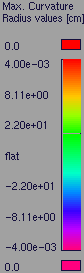
If the +/- band is set to 0.0, the curvature map is relative, and the ramp colors, from left to right, represent increasing curvature values. (The colors are not associated to specific values.)
If you adjust the Curvature Color Scale value, the radius ramp updates.
This mode shows iso-angle lines on surfaces to help you visually evaluate continuity across surface boundaries.
Horizontal/vertical zebra stripe options
This mode shows horizontal or vertical highlights on the surface.
Highlighting helps you find surface flaws by using a color texture to simulate natural highlights. It maps a color pattern onto a surface based on the angle (from 90 to -90 degrees) at which a viewing ray hits the surface.
A common use for highlighting is to identify adjacent surfaces with mismatched tangents. (You can also use Surface continuity for this, but highlighting gives you a clearer view of the surfaces.) Also note that not all Alias packages include the highlighting features.
Some manufacturing processes, like injection molding, need you to design molds. A section of a mold only moves in a certain direction during removal. This direction is the pull vector.
Angle-to-pull is the angle between the surface tangent plane at a surface point and the pull vector. When the angle-to-pull is 0 degrees, the pull vector is parallel to the surface tangent plane at that point. When the angle-to-pull is 90 degrees, the pull vector lies normal to the surface.
Most manufacturing processes require that the angle-to-pull for a molded surface be greater than some angle, for example 1 degree, or else the molded part will not separate from the mold. This angle is the draft angle.
When the angle-to-pull is less than the draft angle, the surface point is out-of-draft. When the angle-to-pull is more than the draft angle, the surface point is in-draft.
This shading mode shows you which parts of a surface are in-draft and out-of-draft for a specified pull vector and draft angle. In-draft points are shaded blue, while out-of-draft points are shaded red. You can also display a tolerance region in pink.
Use one of the tools from the Evaluate > Surface evaluate menu to get an accurate curve-on-surface for the parting line. To see the changes made from the Surface evaluate tool on the draft map, click the surface evaluate shading button again.
If you have scanned an object, and are trying to match the scan data with your NURBS surfaces, the Deviation Map mode lets you know where the two objects deviate. It calculates the distance between a set of meshes and a set of NURBS surfaces, and displays it as a color-coded map, for a quick assessment of the gap’s severity.
Deviation Map can also show the deviation between two sets of surfaces, or two sets of meshes.
This mode acts as a toggle. It only displays the shading once it has been calculated once through the use of Evaluate > Deviation Map .
.
See also Visualize the deviation between mesh-surface, surface-surface or mesh-mesh
This type of surface evaluation provides you with an ability to analyse the safety of a model. It is especially useful with car interior surface design work.
Equally capable of working with meshes and NURBS surfaces, this shading mode enables you to examine a collection of surfaces for potential impact points with a head (represented by a sphere).
The tool internally creates a sphere, to judge where the head could contact the surface model. For example, some spaces, like between the steering wheel and the dash board, are too small for the head to fit into. Only the areas where a head can actually fit in the case of an accident are examined for sharpness and safety issues.
Before analyzing the model, ensure that normals are unified. If they point in different directions, results will be unreliable.
This mode acts as a toggle. It only displays the shading once it has been calculated once through the use of Evaluate > Contact Analysis .
.
This mode shows a user-defined texture reflected on the picked surfaces. You can use one of the two default textures, or load one of your own.
Showroom – Shows a texture map with a showroom reflection.
Photo-Horizon – Shows a texture map with a photo-horizon reflection.
Diffuse – Shows a texture map with a diffuse reflection.
Shade-Sky – Shows a texture map with the reflection of the sky.
Double-horizon – Shows a texture map with a double-horizon image.
User defined – Choose your own reflected texture.


