Aligns a scanned source mesh (from some area of an object) to a destination mesh (or surface) by specifying regions where the data matches on both.
This is useful for updating a digital model based on scan data, after the physical objects have been modified in some areas, and rescanned.
Translate and Rotate – The source mesh can be both translated and rotated during alignment.
Translate Only – The source mesh can be translated only.
Rotate Only – The source mesh can be rotated only.
The source mesh is translated along the selected axes: X, Y and/or Z.
The source mesh is rotated along the selected axis (X, Y or Z), or along all three axes (Free).
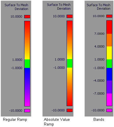
Turn on this option to show the color-coded deviation map.
The color-coded deviation map is only calculated over the selected region(s) on the mesh. The rest of the mesh is shaded in a uniform color.
Maximum distance between source mesh and targets shown on the color ramp. Areas on the source mesh where the deviation is larger than this value are displayed in a solid color (red or purple).
Upper limit for the acceptable deviation between source mesh and target(s). Regions of the source mesh where the deviation is smaller than this value are colored in green.
Where the value of the deviation is between the Acceptable Distance and the Ramp Distance, the surfaces display intermediate colors as shown on the ramp.
The Acceptable Distance also affects the stopping criteria when matching the source mesh to the destination.
Turn on this option if you are not concerned with the direction of the deviation and simply want to view absolute deviation values.
Choose how many sample points are used from the selected regions of the source mesh.
Automatic – Uses an internal number of samples.
By percentage – Uses the Percentage of vertices value to calculate the number of samples.
Percentage of the vertices from the selected regions of the source mesh that are used in the calculation.
A smaller value makes the calculations faster.
This option only appears if Sample density is set to By percentage.
Choose High, Medium, or Low to specify the degree to which overhangs (that is, regions of the source mesh that extend past the destination) are included in the calculations.
If you select Do not change, only the overlapping surface regions are sampled; overhangs are excluded.
In summary, High includes the most overhangs, while Do not change includes the least.
Choose High, Medium, or Low to specify the degree to which local features (for example dips, or bumps) are taken into account in the calculations when positioning the source mesh.
A value of Low helps discard regions where the source mesh or destination presents some dips or bumps that do not have an equivalent on the other.