How to align a scanned source mesh (from some area of an object) to a destination mesh (or surface) by specifying regions where the data matches on both.
This is useful for updating a digital model based on scan data, after the physical objects have been modified in some areas, and re-scanned.
The input to this tool consists of a source mesh, (also referred to as the scan - for example, a re-scanned area of an object), and destination meshes or NURBS surfaces to which the source mesh must be aligned.
The source mesh is transformed so as to minimize the average deviation between the source mesh position and the destination meshes/surfaces.
During the iterative alignment of the scan data, you can restrict the rotation and translation along world space axes, as well as specify a rotation pivot or an axis of rotation.
To ensure fast and accurate results, an area of the source mesh should not have changed, and should match an area on the target object(s). However, the tool will still operate even if these areas are not exactly identical.
To align a mesh to other meshes or surfaces
 ❒.
❒.
The mesh is highlighted in white.
The targets are highlighted in purple.
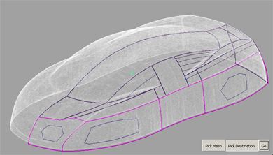
A new series of buttons appears at the bottom of the window.

Method 1: Using regions for positioning
All selected regions are highlighted in blue.
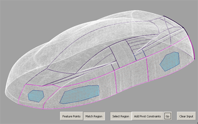
If you do not select any regions, the whole mesh is used.
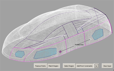
The points you clicked appear as locators lying on the source mesh. You can reposition them with the mouse.
When specifying a rotation pivot or axis, the Transform Mode option is automatically set to Rotate Only to make the results of the re-positioning more predictable.
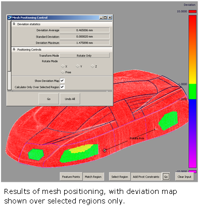
The alignment should improve and the deviation between source and target decrease with each iteration. Note that convergence of the iterations is only guaranteed when Transform Mode is set to Translate and Rotate.
Method 2: Using Feature Points for positioning
Instead of selecting matching regions on both the source and destination geometry, you can also specify matching points.
This method is most useful when the source or destination has features (for example grooves or bumps) not present on the other, or when the source is not already positioned in the vicinity of the destination.
When using this method, Acceptable Distance,Sample density, Percentage of vertices, Increase overlap by sliding mesh, Consider local features and Transform Mode are all ignored. Both translation and rotation are always applied during the positioning.
New buttons appear.

The points appear as numbered bullets: 1,2,...N
The points appear as numbered bullets: 1,2,...N
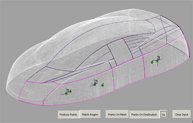
The source mesh is positioned so that the two sets of points achieve the best fit: point N on the source attempting to match point N on the destination.


