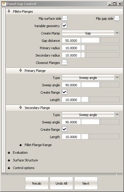
Panel Gap is a new tool found in the palette under Surfaces > Rolled Edge > Panel Gap  . It is a complex tool that aims to create, within a single step, the many surfaces involved in the construction of a panel
gap. This includes defining the gaps between components, the flanges (that define the edges) and the fillets between the main
panel and the edges. The main goals of the tool are efficiency (through a well designed interface) and accuracy.
. It is a complex tool that aims to create, within a single step, the many surfaces involved in the construction of a panel
gap. This includes defining the gaps between components, the flanges (that define the edges) and the fillets between the main
panel and the edges. The main goals of the tool are efficiency (through a well designed interface) and accuracy.
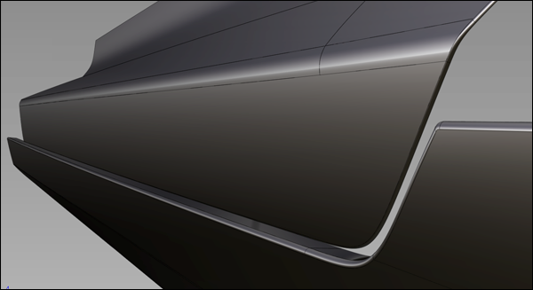
There are several variations on panel gaps, depending mainly on whether the shortest distance (gap distance) is found between the fillets, between a fillet and the flange on the other side, or between the bottom of the flanges.
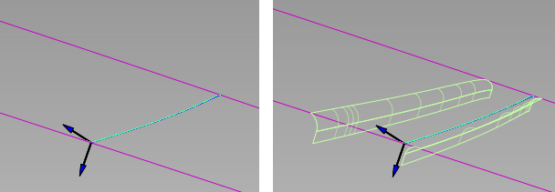
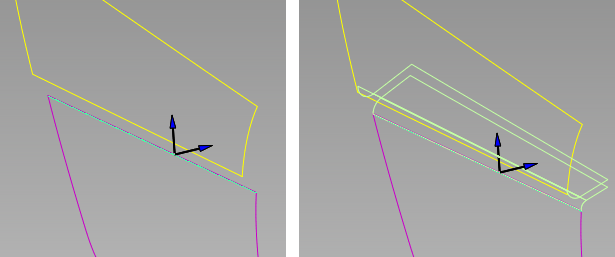
There are two methods that can be used to create the fillets and flanges of the panel gap.
 ❑.
❑.
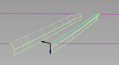
Primary and secondary fillets and flanges are built. The panel surface is automatically trimmed to the edges of the fillets to create the gap.
 and pick one of the output surfaces (fillets or flanges).
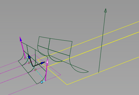
The Panel Gap tool is re-invoked and the control window opens.
Just like with the Fillet Flange tool, the wall is an imaginary surface built off the surface curve, to help define the primary fillet. (The wall is not actually added to the model.)
Instead of having explicit Wall options like the Fillet Flange tool, Panel Gap uses the Primary Flange options.
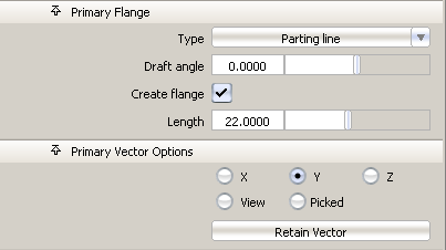
If the primary flange Type is set to Parting line, the wall uses the Primary Vector direction plus the Draft angle as the draft direction. If the primary flange Type is set to Sweep angle, the wall is based on the direction of the surface normal at the selected curve.
The primary fillet and flange are created in the same way as with the Fillet Flange tool.
The primary fillet is always a circular fillet (constant radius fillet) and tangent continuous with the panel surface. You can specify its radius (Primary radius) in the control window. The fillet is built between the panel surface and the (imaginary) wall.
The location of the secondary fillet is calculated from the values of the Primary radius, Gap distance, and Secondary radius provided in the control window.
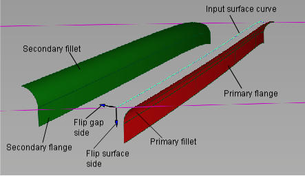
The Flip surface side checkbox reverses the direction of the fillets and flanges. It has the same effect as clicking the blue arrow that appears normal to the panel surface.
The Flip gap side checkbox lets you switch the direction of the fillet in order to position the gap on the other side of the surface curve. There is a corresponding blue arrow on the model that you can click to switch the direction as well.
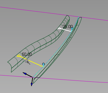
The Gap distance option determines the initial width of the panel gap. The gap corresponds to the shortest distance between the primary and secondary rolled edges.
When Variable geometry is turned on, you can click on the input surface curve(s) to position manipulators that allow you to vary the Gap distance, the direction of the Primary Vector, or the direction of the Secondary Vector (depending on the setting of Create Manip) along the length of the gap.
The primary vector controls both the draft direction and the primary flange direction. These manipulators appear as purple arrows. The secondary vector controls the secondary flange direction. These manipulators appear as yellow arrows.
Each manipulator consist of two handles, one at each end. Click on a handle to change its value (it turns white) or simply
roll over it to see the value (it turns yellow). Hold  and click on a manipulator to remove it.
 .
.
.
. 
The gap widths between the edge of the panel and the first manipulator, as well as between the opposite edge of the panel and the last manipulator, are constant. The width between any pair of interior manipulator is interpolated.
. 
For both Primary Vector and Secondary Vector manipulators, the vector direction between the edges of the panel and the nearest manipulator remains constant. Between any pair of interior manipulators, the vector direction is interpolated.
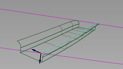
Turning on Closeout Flanges creates a ruled surface joining the bottom edges of the primary and secondary flanges (when both are present).
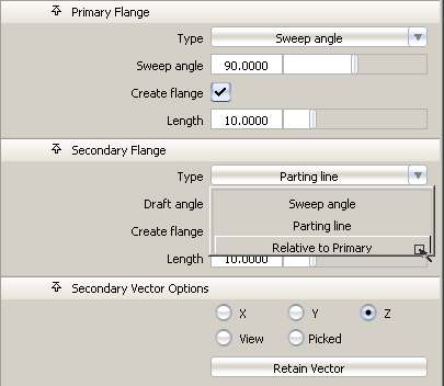
The primary flange offers the same options as in Fillet Flange. It can be defined by a Sweep angle (angle between the flange and the input surface) or a Parting line direction (specified through the Primary Vector Options) plus a Draft angle.
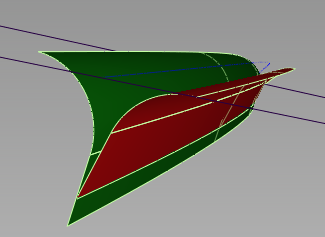
The options for the secondary flange are exactly the same as for the primary, with the addition of a third Type called Relative to Primary. This lets you change the Draft angle or Sweep angle of the secondary flange relative to the first flange. This is useful when you want to create a gap with zero width and coincident flanges, as shown below.
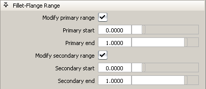
Turning on Modify Primary Range and Modify Secondary Range in the control window causes arrow manipulators to appear on the fillets. Drag these arrows to modify the extent of the fillets and flanges across the main panel. You can drag the arrows all the way to the edges of the input surfaces. Setting the sliders to 0.0 and 1.0 resets the original extent.
When the boxes are unchecked (default), the fillets and flanges extend to the edges of the input surfaces.
Using the Primary/Secondary start and end sliders in the control window achieves the same effect.
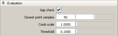
Turn on Gap check to show a deviation comb, as well as minimum and maximum deviation at the gap location.
Additional options appear to let you control the deviation locator.
The Threshold acts as a tolerance, and is most useful in the case of a constant gap width. If the gap is within that value of the requested Gap distance, the deviation quill is green, otherwise it is red.
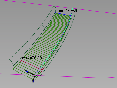
Here Gap distance = 50.0 and Threshold = 0.1
These controls apply to both primary and secondary fillets and flanges simultaneously. They are the same as in Fillet Flange.
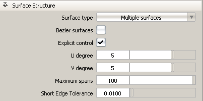
The U Degree, V Degree and Maximum spans for both the fillet and flange can be modified by turning on Explicit Control in the Control options and adjusting the appropriate sliders.
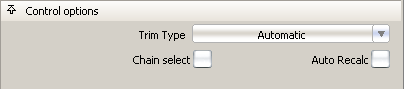
Turning on Chain Select lets you select tangent continuous surface curves all at once.
Auto Recalc does the usual and re-calculates the output surfaces automatically when you change an option or move a manipulator.
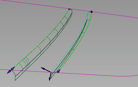
When Trim Type is set to Automatic, the panel surfaces (surfaces from which the fillets and flanges are built) are automatically trimmed to the edges of the fillets, if the fillets extend to the ends of the surfaces. You may need to use the Fillet-Flange Range options to extend the fillets, as shown below.
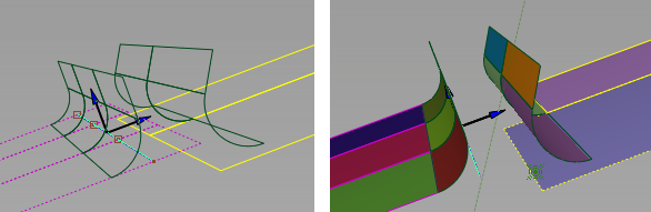
Left: Trim Type is Off. Right: Trim Type is Automatic, but secondary fillet does not reach to the edge of the panel.
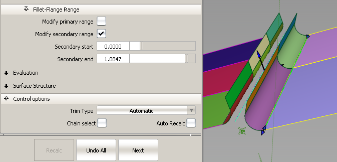
The secondary fillet is extended, allowing the panel surface to be trimmed.
If Trim Type is set to Curves on Surface, curves-on-surface are placed on the panel surfaces at the fillets edges, but no trimming occurs.


