


The following workflows describe how to use the new Align tool that we introduced in AliasStudio 2009. To use the previous version of the tool (renamed Align 2008), see Workflows for Align 2008.
Like its predecessor, the new Align tool moves or reshapes a curve or surface to achieve positional, tangent, or curvature continuity with another curve or surface. However it does so using a simplified interface, and direct interaction through the use of manipulators. It also provides superior output.
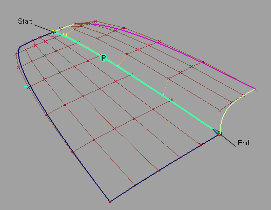
This aligns one surface to another surface edge, trimmed edge, curve-on-surface, or isoparametric curve.
 ❒.
❒.
When the value of the slider is 0.0, the surface being aligned keeps its parameterization intact. As the slider is moved to 1.0, it attempts to match the parameterization of the Master surface, which results in a better fit.
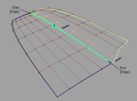
Manipulator arrows allow direct manipulation of the tangent and curvature lengths.
The arrows on the outside of the surface provide independent scaling of the tangent and curvature lengths on each side. The arrow in the middle of the tangent or curvature row moves all the CVs in that row by the same amount.
If the requested continuity is not achieved, try one or more of the following:
Here Position Influence has been set to 1.0 and Explicit Control turned off to match the degrees. Notice how the CVs now line up perfectly across the boundary.
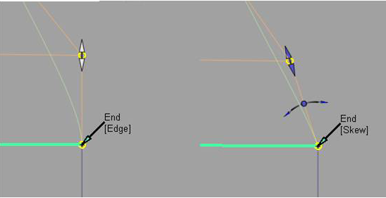
When Skew is selected, a rotational manipulator becomes visible which allows direct modification of the skew angle. You can also specify a specific Skew Angle value in the option window.
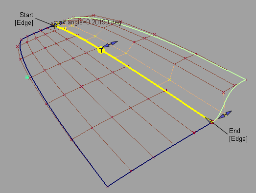
When Edge Align is selected and you are aligning to a natural surface boundary, you can turn on Tangent Balance to adjust the CVs on the tangent row so that the tangent lengths of the Input surface match those of the Master. The same applies to the curvature row CVs if G2 Curvature is on.
 ❒.
❒.
The first surface is aligned to the closest points on the second surface.
The Partial manipulators will change from a double sided arrow to a single arrow when they snap to the end of the Master surface.
You can also use the Start Partial and End Partial sliders in the option window.
Blending extends the influence of the blend further into the surface or curve.
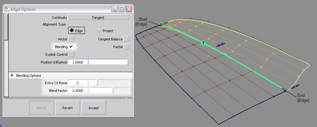
Two rows beyond the tangent row are affected by the Blend factor.
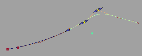
Align using a directional constraint (Vector alignment)
Once a positional alignment has been established, the tangent and curvature rows can be aligned with a vector (directional) constraint.

Watch Aligning using a vector constraint.
The tangent and/or curvature CVs are modified along the vector to create the required level of tangency or curvature.
If the alignment cannot be maintained with your choice of directional constraint, the edges of the aligned surface appear as dashed lines.
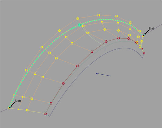
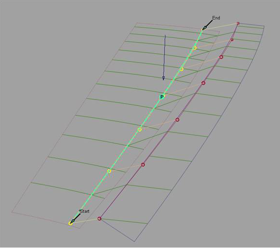
Align by projecting an edge onto a surface (Projection alignment)
A surface can be aligned to the inside of another surface by projecting the edge along a vector down to the Master surface
❒.
The edge is projected along the defined vector onto the Master surface. A curve-on-surface is created as well, and can be used later for trimming the Master surface.
Modification of the projected edge can be made after the alignment by modifying the CVs with Control Panel > Transform CV.
Align a surface edge to an entire curve
This aligns the length of the surface edge to the length of the curve.
❒.
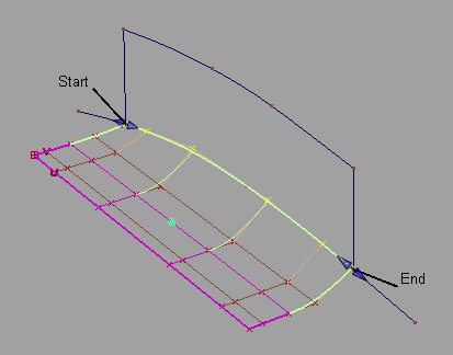
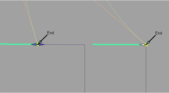
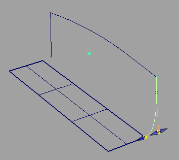
Align a curve end to a surface edge, isoparm, or curve-on-surface
This aligns the end of the curve to the end of the surface curve.
❒.
The Alignment Type option becomes available. U/V is the default and aligns the free curve to the direction of the surface curve that you selected as the Master.
The tangent and curvature alignment are then defined by the tangent plane to the surface at the point of contact, and the direction of the vector specified through Vector Options
Alignment Type = Vector: This is equivalent to creating a curve-on-surface on the surface, and aligning the free curve to it.
❒.
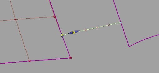
Manipulator arrows become available, allowing direct manipulation of the attach point location, as well as tangent and curvature scaling.
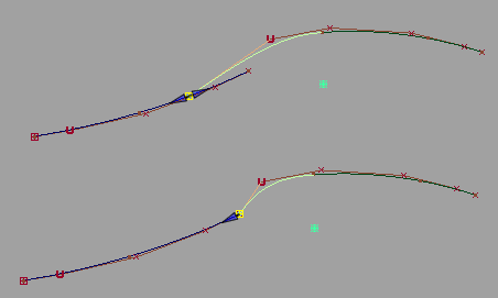
Aligning curves with positional continuity and modifying the Attach Point.
Aligning curves with curvature continuity.
Align both ends of a curve or surface
When aligning both ends of a curve, or opposite edges of a surface:
 retrieves the construction history for the end closest to where you click, allowing you to edit the alignment at both ends.
When a curve or surface is aligned to two masters, it has a single history item as seen with Windows > Information > History View. In this case, clicking the Revert button first reverts the active side (the one you last aligned). The history then applies only to the remaining side. Clicking Revert again deletes the history and returns the input geometry to its original shape.
 +
+  +
+