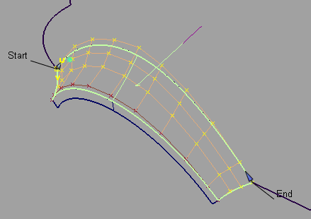
Aligns a curve or surface edge to another curve, or surface edge. Also aligns an edge to the interior of a surface.
See Workflows for the new Align tool.
Edge – This option is the default and provides alignments for all surfaces when a vector constraint is not used. This includes the alignment of a surface to a surface edge, isoparm, or curve-on-surface (CoS).
Project – This option aligns an edge to a surface by using a projection vector (along the current view by default). It is not necessary to have a curve-on-surface already on the surface to align to it. The curve-on-surface is created automatically.

If Project is selected, a Vector Options section appears to let you define a vector. The default vector direction is based on the current view. (See Vector Options.)
U/V – This option only appears when aligning a curve to a surface.
The curve is aligned to either the U or V direction of the surface.
Vector – This option only appears when aligning a curve to a surface.
The tangent and curvature alignment is defined by the tangent plane to the surface at the point of contact, and the direction of the vector specified through Vector Options. That is, the tangent and curvature CVs on the curve are only allowed to move in the direction of the vector. This is the equivalent to creating a curve-on-surface on the surface, and aligning the free curve to it.
If the vector is set to View, the shape of the curve in the given view remains the same through the alignment, while maintaining the desired level of continuity with the surface.
This checkbox is only available when aligning a surface to another surface with Alignment Type set to Edge and Continuity set to Tangent or Curvature.
When Vector is checked on, positional continuity is achieved first, then the tangent and curvature CV rows are constrained to move along the selected vector. (See Vector Options.)
This option only appears when Continuity is set to Tangent or Curvature and the following conditions apply:
When checked on, the CVs of the tangent row are adjusted so that the ratio of the start and end tangent lengths on the Input surface matches that of the Master. The same applies to the curvature row CVs if Curvature is on. The inside CVs are also adjusted so that the Input’s hull (for the tangent and curvature rows) mimics the shape of the Master’s.
Tangent Balance is off.
Tangent Balance is on. The hull shape of the Input reflect that of the Master.
The tangent and curvature lengths can be scaled in a proportional way so as not to change the shape of the Input surface, by using the Tangent Scale and Curvature Scale sliders (or corresponding manipulators). These sliders are only available when Tangent Balance is on, but retain their values if Tangent Balance is toggled off then on again.
This option applies to both Input curves and surfaces. It moves the inner rows of CVs to even out the modification in the Input. You can adjust the number of Extra CV Rows that get modified and the Blend factor to get the desired effect. The rows of CVs needed to maintain continuity are not touched.
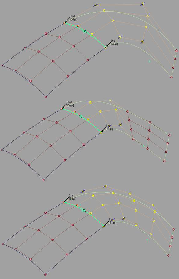
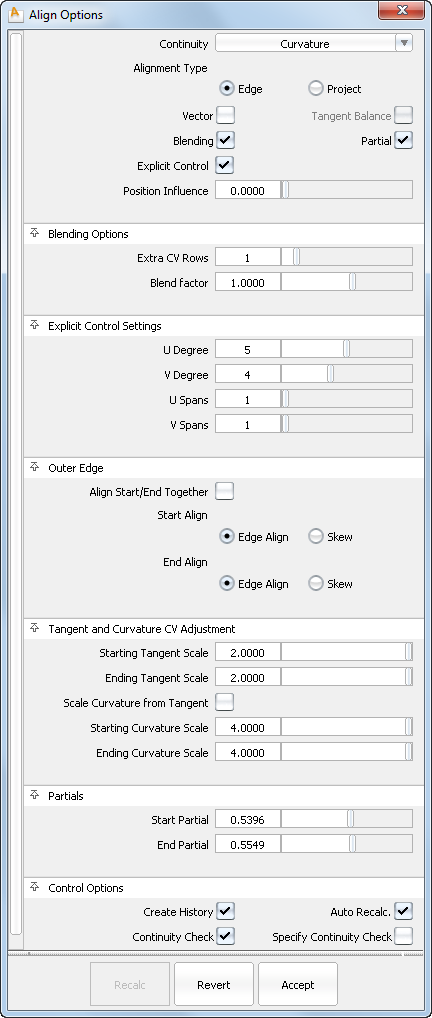
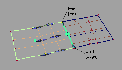
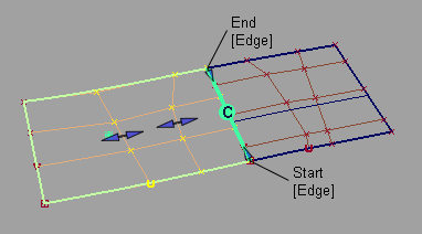
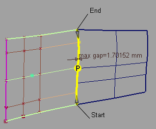
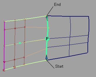
The Partial checkbox is always off by default when a surface is aligned. Initially, the input surface’s edges are aligned to the full extent of the master’s edge. If Partial is turned on, the closest points on the master surface’s edge (or curve) are used.
The Partial Join manipulators are always displayed. Use the manipulators (or the Partials sliders) to control the extent. The Partial option applies when a surface edge is aligned to another surface edge, isoparm, curve-on-surface, or free curve
Partial is turned off automatically if the manipulators are dragged to the ends of the master’s edge. It is turned on automatically when the manipulators are dragged away from the ends.
Turning on Partial always resets the manipulators to the closest points on the master’s edge. Conversely, turning off Partial sets the manipulators to the ends of the master's edge.
Checking on this option gives you access to the Explicit Control Settings where you can adjust the degree and number of spans for the Input. These settings only appear once both the Input and Master geometries have been selected. The degree and span settings initially correspond to those of the Input curve or surface.
Increasing the degree or adding spans can provide greater flexibility for the curve or surface to align to continuity, or create a more subtle blend. Explicit Control is checked on by default.
If Explicit Control is not checked, the alignment will first raise the degree of the Input to match that of the Master, before attempting to insert spans to achieve continuity.
This slider only appears when Alignment Type is set to Edge and Vector is off.
When Position influence is set to 0.0 (default), the alignment process attempts to maintain the parameterization of the Input surface. This alignment will not cause any CV movement provided the fit is already within the Curve Fit Distance tolerance. If the edge needs to be refit, there may be minimal CV movement.
When Position influence is set to 1.0, the alignment attempts to match the parameterization of the Input surface to the parameterization of the Master as closely as possible. This alignment has more freedom to produce a closer fit (better continuity), but can cause the lateral spacing of position, tangent, and curvature CVs on the Input to change. However, tangent and curvature lengths are not affected by Position Influence.
The slider provides for incremental interpolation between maintaining parameterization on the Input and providing continuity with the Master.
Position Influence = 0. Positional continuity not achieved.
Position Influence = 1.0. Positional continuity achieved.
The degree to which the influence of the alignment decreases or increases as it moves out to the extra CV rows. (This option is only available if Extra CV Rows is greater than zero.)
A positive value indicates that the influence decreases exponentially. The higher the value, the more rapidly the influence drops.
A zero value indicates no drop in influence; the change is constant row by row.
A negative value indicates that the influence increases exponentially. The higher the absolute value, the more rapidly the influence increases.
The following section only appears when Alignment Type is Edge, and Continuity is set to Tangent or Curvature.
These options control the direction of the tangent (within the tangent plane) along the outer edges of the Input surface.
The following section only appears when Continuity is set to Tangent or Curvature.
These options control the length of the tangent or curvature. You can also use the tangent and/or curvature manipulators to adjust those values.
Tangent and Curvature CV Adjustment
This slider value lets you adjust the true length of the tangent (in centimeters) at the aligned end of the Input curve.
When aligning surfaces, if Tangent Balance is on, this slider lets you scale the tangent lengths in a proportional way, so as not to change the shape of the surface. It retains its value if Tangent Balance is toggled off then on again.
This slider value lets you adjust the true curvature length at the aligned end of the Input curve.
When aligning surfaces, if Tangent Balance is on, this slider lets you scale the curvature lengths in a proportional way, so as not to change the shape of the surface. It retains its value if Tangent Balance is toggled off then on again.
These sliders values range from 0.0 to 1.0 and specify the percentage of the way that the start or end of the Input surface extends from the end of the Master surface (in parameter space).
These values can also be adjusted by using the Partial slider manipulators along the boundary. The manipulators indicate they have been positioned at the full extent of the edge of the Master by displaying only the internal arrow. Double arrows indicate that the Input edge is not positioned at the full extent of the edge of the Master.

The Partial slider manipulators also snap to the options set in the Snap Options window (except for Snap to Center and Pivot).
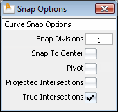
See Curve Snap Options.
Saves the construction history of the alignment so you can edit the aligned objects or the tool options and the alignment automatically updates.
When a curve or surface is aligned to two masters, it only has a single history item.You can still edit both Align operations separately by using Object Edit > Query Edit and clicking near the appropriate end/edge of the aligned geometry.
Each time the Accept button is clicked, a configuration of the tool and the current Input geometry is saved.
The Restore button is only available when the Accept button has been clicked at least once. Each time the Accept button is used, the state is stored, and can be retrieved by using the Restore button. This way, it is possible to append a series of alignment operations.
Edit > Undo ( +Z (Windows) or
  +Z (Mac) ) can be used multiple times to restore modifications to the scaling of tangency, curvature, or partial edge location.
Undo lets you explore modifications and still return to a preferred alignment. Undo cannot be used immediately after clicking
Accept or Restore.
+Z (Mac) ) can be used multiple times to restore modifications to the scaling of tangency, curvature, or partial edge location.
Undo lets you explore modifications and still return to a preferred alignment. Undo cannot be used immediately after clicking
Accept or Restore.
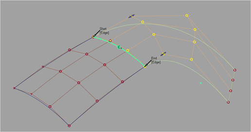
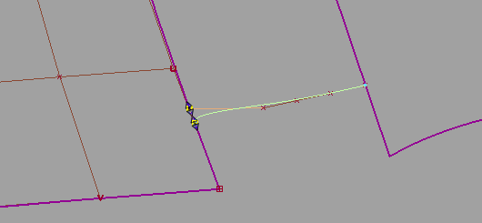
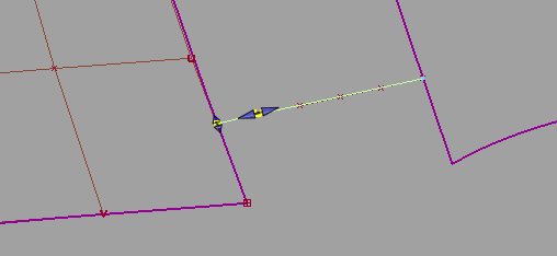
The manipulators appear as small arrows or double arrows, except for Skew which is an arc with a small circle. Once the manipulator is engaged by clicking the arrow or circle, mouse contact is not required to make further modifications.
The following values can be adjusted directly through manipulators:
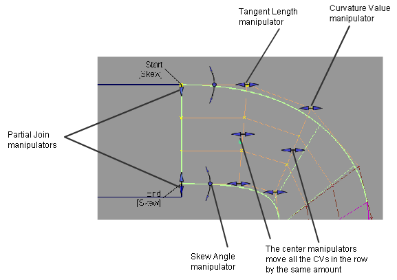
Surface alignment manipulators

Curve alignment manipulators


