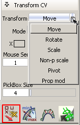
We have added new functionality to the Move CV tool (located in the Control Panel) and provided a Hot Spot interface to reduce mouse movement when doing direct surface manipulation.
Given the tool's expanded functionality, we have renamed it Transform CV. The new name is used in the descriptions below.
When the Control Panel > Transform CV  tool is selected, holding down the space bar displays the Hot Spot interface under the cursor.
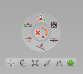
The transform tools are available in the horizontal ribbon, and the different modes that apply to the selected tool are displayed on the wheel. The center spot is divided into two halves: CV and Hull. Roll-over an icon to see a description of what it does.
tool.
The Hot Spot interface appears
The Hot Spot interface disappears.
New tools added to Transform CV in this release are: Rotate, Scale, Non-p scale, Pivot and Prop mod. Having these additional transformations available from within Transform CV also saves you mouse mileage when modifying surfaces by direct CV manipulation.
The Move tool has a new mode called VIEW. This mode moves CVs in the plane of the current view.
 = Unconstrained movement in the current plane defined by the direction of the view.
 = Movement constrained to the horizontal axis of the screen.
 = Movement constrained to the vertical axis of the screen.
The PARA mode behaves like the old Parallel option (check box) of the PROJ mode, so it is not really a new tool.
The Prop mod tool has modes: XYZ, NUV, SLIDE, ROT (Rotate), and NPSCL (Non-p scale).
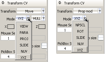
The Rotate, Non-p scale and Pivot tools do not have any modes.
Below is a description of the new tools:
This tool behaves like the Transform > Modify > Proportional Mod  tool, but its user interface has been enhanced to be more intuitive and easily allow experimentation with falloff values.
See the next section for details.
Integration of Proportional Mod tool into Transform CV
The Prop Mod tool available from Transform CV is an improved version from its namesake in the Transform tab. Using this version of the tool provides the following advantages:
Specifying the selection range
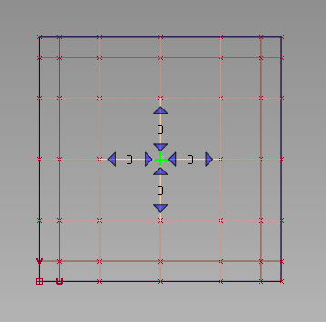
You must first select the primary CV by clicking on it. The primary CV defines the point from which falloff is calculated and applied to the range of CVs. It is indicated by a green jack locator.
If only one CV is selected when the Prop Mod tool is invoked, it becomes the primary CV.
Small blue arrows appear around the primary CV, allowing you to select/deselect additional rows of CVs to define the range that will be affected by Prop Mod.
If you keep the mouse button depressed, rows of CVs are continuously added/removed to/from the selection. if you click and release, rows are added/removed one at a time.
A numeric label shows how many CVs/rows of CVs have been selected for each direction.
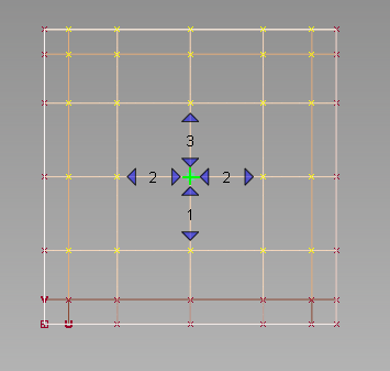
Selecting and de-selecting CVs always maintains a “rectangular” selection.
Instead of using the blue arrows, you can also select the range of CVs by holding down the  key, and:
There are still five modes, but Smooth has been replaced by SLIDE in the Transform CV version of the tool. Modes XYZ, NUV, ROT (Rotate), and NPSCL (Non-p scale) remain the same.
The mode can be changed from the Mode drop-down in the Control Panel, or by using the Hot Spot interface. The Hot Spot interface appears under the cursor when you hold down the space bar. See To use the Hot Spot interface above.
As with the Transform > Modify > Proportional Mod tool, we use a range-based modification. That is, the greater the number of CVs between the primary CV and the boundary of
the defined region, the less effect the transformation has on each CV.
The falloff window appears as soon as the Prop Mod tool is selected.
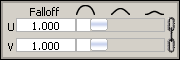
By default the U and V falloff sliders move in sync. To decouple them, click the chain link icon on the right hand side of the window. A value of 0.0 means that all CVs move by the same amount. A value of 1.0 (default) corresponds to a linear falloff. The higher the falloff value, the less effect the movement of the primary CV has on the surrounding CVs.
The slider settings are maintained between applications of the tool.
Applying Prop Mod across multiple surfaces
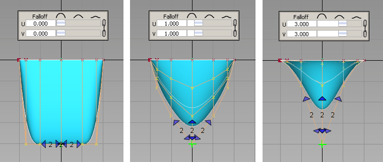
Under certain conditions, it is possible to select CVs on surfaces adjacent to the surface containing the primary CV and apply the modification across several surfaces.
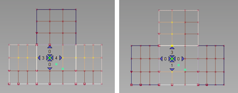
Figure A: Four adjacent surfaces.
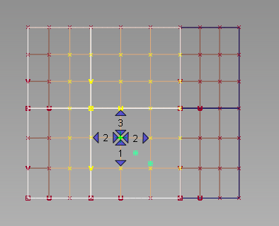
Figure B: Six adjacent surfaces forming a rectangular grid.


