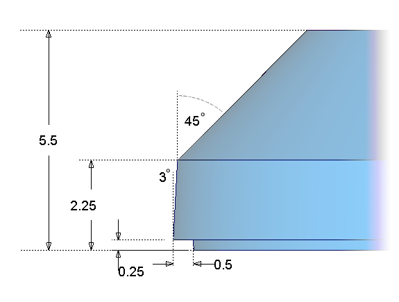
The design of the MP3 player features chamfered sides. You will now use the Draft and Flange tools to create the side surfaces and a split-line feature.
The dimensions for the casing are shown below.
Opening the tutorial file (optional)
If you successfully completed Part 1, proceed to the next step: Creating the Side Surfaces, below.
If you were not successful in part 1, open the file called MP3Player_part2.wire, located in the wire directory of the CourseWare project. This file contains the completed model from Part 1.

Watch Part 2 of the tutorial.
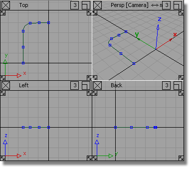
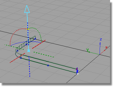
First, you will move your curves away from the center line in the z-direction. This will leave some space for a split-line feature you will create later in the tutorial.
 and drag a pick box over
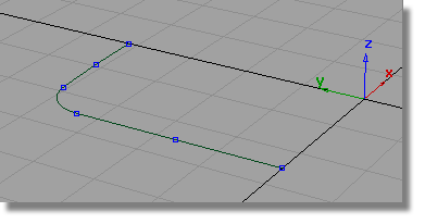
all the curves to select them
and drag a pick box over
all the curves to select them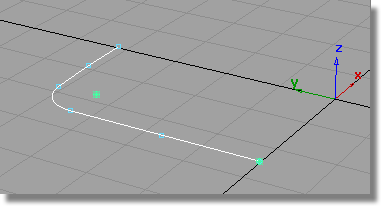
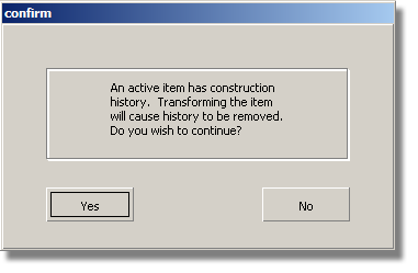
You will be asked about losing construction history, which relates to the fillet curve. Answer Yes.
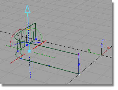
Now you will create the side wall using the Draft surface.
 . Double-click the icon to
open the option window. You will start with the default Draft settings,
and then modify them after the surface is created.
. Double-click the icon to
open the option window. You will start with the default Draft settings,
and then modify them after the surface is created.
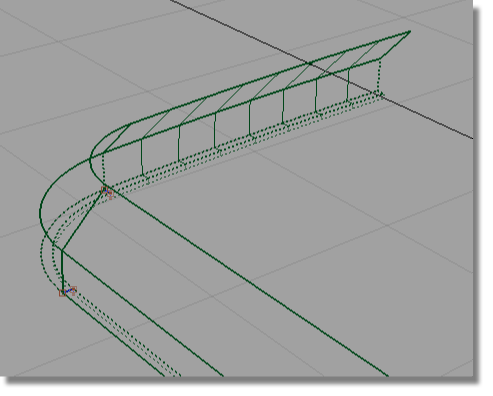
The default Draft surface is built. The default draft direction is in the positive z-axis, which is correct for your design.
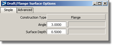
Now you will modify the Draft Angle and the Surface Depth to match the required dimensions.
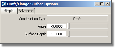
The Draft surface is rebuilt to the new settings.
 to complete the surface
creation.
to complete the surface
creation.
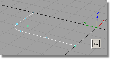
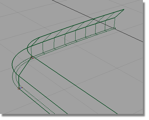
Now you will build the chamfered surfaces.

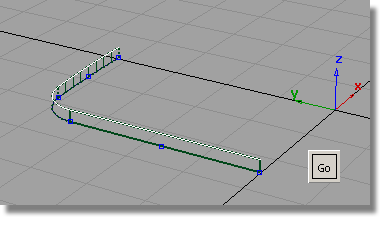
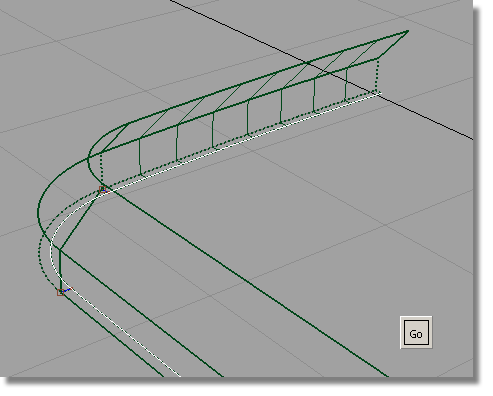
Click Go to create the chamfered surfaces.

to complete the Draft surfaces.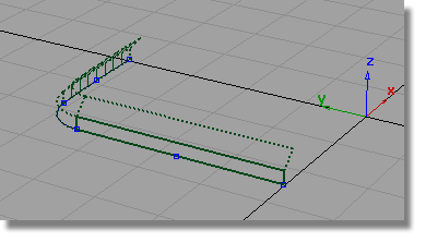
Next you will use the Flange surface to create the small split-line feature at the center line.
The Flange surface can only be built from a surface edge, not a curve. This is because it measures its angle from the surface edge, not from a draft direction. So first, you will template your curves to make it easier to select the surface edges.
 and modify the options so
that only curves will be selected.
and modify the options so
that only curves will be selected.
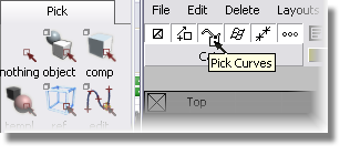

 to turn the curves into
a template that will not be selected by the Pick
> Object tool.
to turn the curves into
a template that will not be selected by the Pick
> Object tool.
Now you will create some small Flange surfaces to represent the split-line detail.
. Double-click the icon to
open the option window. Change the Construction Type from Draft to Flange.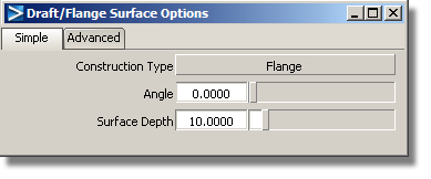

The small flange surfaces are created.
to complete the Flange surface.
To finish off the sidewalls, you will now create another set of flange surfaces to meet the center-line.
again, double-click the
icon to open the option window.
Change the Angle to 0 and the Surface Depth to 0.25.

to complete the Flange surface.
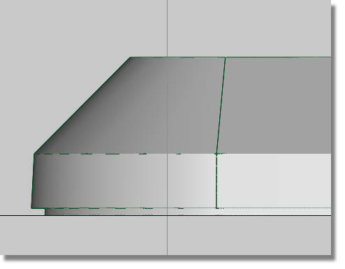
The side profile of the surfaces shows how the draft angles and split-line detail have been accurately created.
 and drag a box over all
the surfaces to select them. You can delete these, as they aren’t
needed.
and drag a box over all
the surfaces to select them. You can delete these, as they aren’t
needed.
 to save the current scene.
For information on creating the Lessons project, or saving your work, see Saving your work in a Windows environment or Saving your work in a Mac OS X environment.


