


Using Basic Polygon Editing
to Create an Upper Cabinet
Now you will use many of the techniques from the previous lesson to create an upper cabinet.
Create the upper left cabinet board:
 select the base cabinet
and on the
select the base cabinet
and on the  Modify panel, rename the
object LoCab_18.
Modify panel, rename the
object LoCab_18.
 Create panel, click
  (Geometry), then on the
Object Type rollout, click Box.
(Geometry), then on the
Object Type rollout, click Box.
Referring to our diagram, you can see that the length of the board you will specify in the next step should be 11 3/4”.
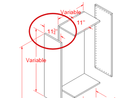
The height for upper cabinets of this design is variable, to account for the presence of appliances, sinks, windows, and so on. In this case, the upper cabinet will be installed on a wall with nothing between it and the base cabinet, so you will give it a height of 39”. You will specify this height as a negative value, so you can better position the cabinet as part of the total 93” allowable space.
Modify panel, and on the
Parameters rollout, set Length to 11.75, Width
to 0.75, and Height to –39.0.
Keep in mind that as soon as you type in the values, 3ds Max Design converts the decimal portions to multiples of 1/32”.
 (Select And Move), then set
the Z transform value to 93.0.
(Select And Move), then set
the Z transform value to 93.0.
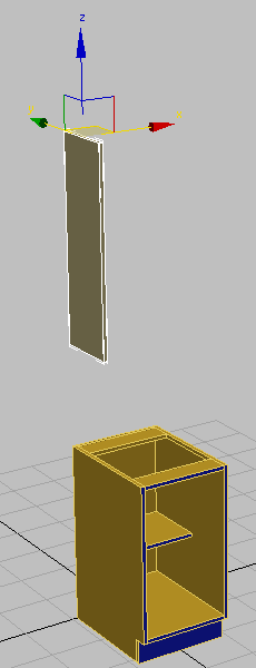
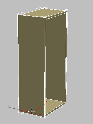
The top of the box is now above the base cabinet at the proper height.
 (Zoom Extents).
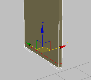
Now you need to align the box with the left side of the lower cabinet.
 (Align), then in the viewport,
click the lower cabinet.
(Align), then in the viewport,
click the lower cabinet.
 Align Position (World)
group, make sure X Position is on and Y Position and Z Position
are off. In the Current Object group, choose Minimum and in the
Target Object choose Minimum, then click Apply.
Align Position (World)
group, make sure X Position is on and Y Position and Z Position
are off. In the Current Object group, choose Minimum and in the
Target Object choose Minimum, then click Apply.
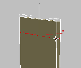
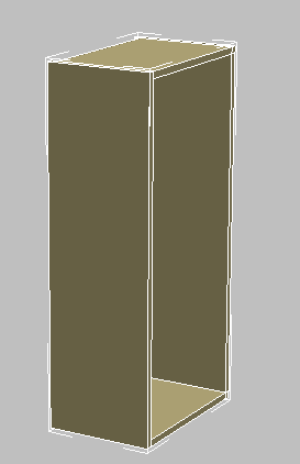
Left panel of upper cabinet aligned with left panel of lower cabinet
Convert To Editable
Poly.
Polygon Modeling panel, turn on  (Edge).
Edit panel, click
(Edge).
Edit panel, click  (Swift Loop) to turn it
on.
(Swift Loop) to turn it
on.
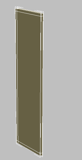
A green virtual loop will now display as you position your cursor near an edge, to help you visualize loop placement.
3ds Max Design creates an edge loop that is perpendicular to the edge you clicked.
(Select And Move), then set
the Z transform spinner to 92.25.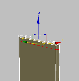
(Swift Loop) again.
(Select And Move), then set
the Z transform spinner to 54.75.
This value represents the distance from the floor to the top of the board, (93”), less the height of the board itself (39”), plus the width of the board cut line you want to create (–0.75”).
(Swift Loop) again.
(Select And Move), then set
the Y transform spinner to –0.75.
This value represents the cut line for the 0.75-inch back board you will soon create.
You now have all the divisions required to build upon this cabinet component.
Polygon Modeling panel, turn off  (Edge) to exit sub-object
selection.
(Edge) to exit sub-object
selection.
Create a second cabinet board:
Object
group, choose Copy, and then click OK.
 Move the cloned board on
its X axis slightly to the right.
Move the cloned board on
its X axis slightly to the right.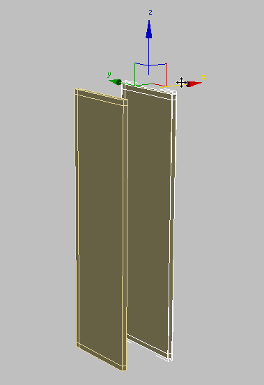
(Align).
Align
Position (World) group, make sure X Position is on and Y Position
and Z Position are off. In the Current Object group, choose Maximum,
and in the Target Object group, choose Maximum, then click OK.
Select the upper left-hand
cabinet board (the original board), and on the ribbon Geometry panel, click  (Attach), then click the
cloned board.
(Attach), then click the
cloned board.
Create the top, bottom, and back boards:
Polygon Modeling panel, click  (Polygon).
Click and Ctrl+click to select the polygons
that form the attachment points for the right-hand board.
(Polygon).
Click and Ctrl+click to select the polygons
that form the attachment points for the right-hand board.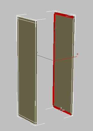
 Orbit the view, then Ctrl+click
to select the corresponding polygons on the left panel.
Polygons panel, click
Orbit the view, then Ctrl+click
to select the corresponding polygons on the left panel.
Polygons panel, click  (Bridge).
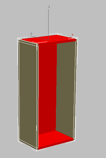
Bottom, top, and back panels created from selected polygons
Orbit a little more to get
a better view of the side of the cabinet.
Polygon Modeling panel, click (Edge).
Modify Selection panel, click  (Loop Mode).
select the loops shown in
the following illustrations, and on the ribbon Loops panel, Ctrl+click
(Loop Mode).
select the loops shown in
the following illustrations, and on the ribbon Loops panel, Ctrl+click  (Remove Loop) to remove
the loops and their vertices.
(Remove Loop) to remove
the loops and their vertices.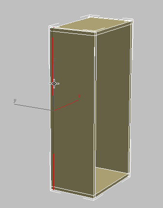
(Edge) again to exit the
Vertex sub-object level.
Orbit the scene until you
can see the front of the cabinet.
Create panel, click (Geometry), then on the
Object Type rollout, click Box.
Like the shelf you created for the base cabinet, this value represents the full width of the cabinet (18 inches), less a 3/4 inch width of each side board, less another 1/8 inch space to provide room to remove the shelf, if needed.
Set Length to 10.5, which will be the depth of the shelf, and Height to 0.75, which is the thickness of the cabinet boards.
(Align), then in the viewport,
click the upper cabinet.
Align Position (World)
group, turn on X Position, Y Position, and Z Position, and in the
Current Object and Target Object groups, choose Center, then click OK.
Move the shelf on its Y
axis until it touches the backboard. This adjustment is easiest
in the Top viewport.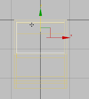
Shift+move
the shelf upward on its Z axis, and in the Clone Options dialog Objects group, make
sure Copy is on, then click OK.
Adjust the height of the
two shelves until they are spaced apart equally.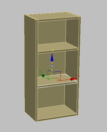
Select the cabinet.
Polygon Modeling panel, click Modify Mode
to turn it on. On the Geometry panel, click (Attach), then click the
two shelves.
Next, you will assign material IDs to the polygons so they can receive different sub-materials.
 (Material Editor) to open the
Compact Material Editor.
(Material Editor) to open the
Compact Material Editor.
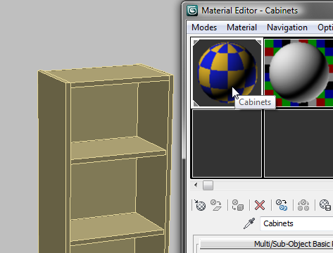
Dragging and dropping is an alternative way of applying materials.
 Close the Compact Material
Editor.
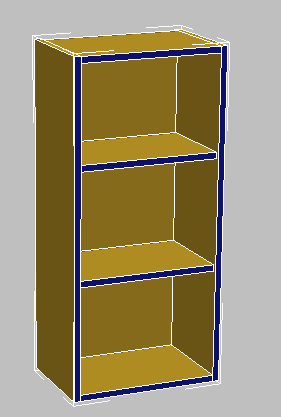
Polygon Selection panel, activate (Polygon).
Properties panel drop-down portion, click
Close the Compact Material
Editor.
Polygon Selection panel, activate (Polygon).
Properties panel drop-down portion, click  (MatIDs).
 Close the Set ID dialog.
click and Ctrl+click to select the polygons
that face forward, as shown in the next illustration.
Close the Set ID dialog.
click and Ctrl+click to select the polygons
that face forward, as shown in the next illustration.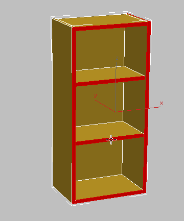
drop-down portion, click (MatIDs) once more, and
on the Set ID dialog, type 2 in the Set
ID field, then press Enter.
Close the Set ID dialog.
Polygon Selection panel, click  (Polygon) to exit the Polygon
sub-object level.
(Polygon) to exit the Polygon
sub-object level.
Finally, modify the upper cabinet so that its local coordinates, represented by its pivot point, are the same as those of the lower cabinet. This way, the next time you want to place the upper cabinet in the scene, it will be positioned at the correct height in relation to the floor and in line with the lower cabinet.
 Hierarchy panel, and in
the Adjust Pivot rollout Move/Rotate/Scale
group, click to turn on Affect Pivot Only.
(Align), then click the lower
cabinet.
Align Position (World)
group, turn on X Position, Y Position, and Z Position and in the
Current Object and Target Object groups, choose Pivot Point, then click
OK.
Hierarchy panel, and in
the Adjust Pivot rollout Move/Rotate/Scale
group, click to turn on Affect Pivot Only.
(Align), then click the lower
cabinet.
Align Position (World)
group, turn on X Position, Y Position, and Z Position and in the
Current Object and Target Object groups, choose Pivot Point, then click
OK.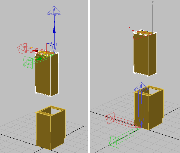
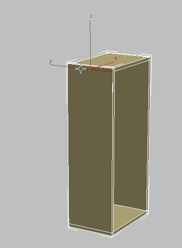
Left: Upper cabinet before pivot alignment
Right: Upper cabinet after pivot alignment
Hierarchy panel Adjust Pivot rollout Move/Rotate/Scale group,
click to turn off Affect Pivot Only.
Select the upper cabinet
and on the Modify panel, rename the
object HiCab_18_39.
 open
open