


Import the Model into 3ds Max Design
Now you have a model that you can import into 3ds Max Design.
Import the SAT model into 3ds Max Design:
 3ds Max Design.
 Project Folder and set your
current project to Autodesk 3ds Max Design 2011 Tutorials.
Project Folder and set your
current project to Autodesk 3ds Max Design 2011 Tutorials.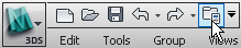
 Units Setup. On the Units Setup dialog,
choose Metric, and then choose Millimeters from the drop-down list.
Click OK.
Units Setup. On the Units Setup dialog,
choose Metric, and then choose Millimeters from the drop-down list.
Click OK.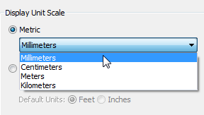
 Application menu, choose
Import. In the Select File To Import dialog, navigate to the \import\Inventor_files folder,
highlight my_blade_clamp.sat,
and then click Open.
Application menu, choose
Import. In the Select File To Import dialog, navigate to the \import\Inventor_files folder,
highlight my_blade_clamp.sat,
and then click Open.
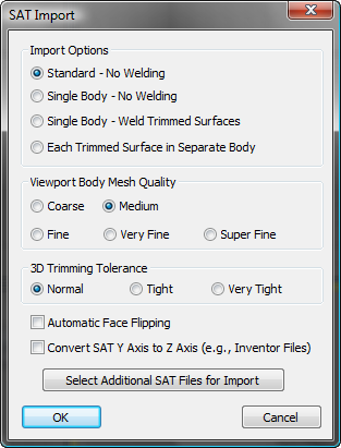
3ds Max Design opens the SAT Import dialog.
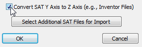
In Inventor, the up-axis is Y, rather than Z as it is in 3ds Max Design. So when you move a file from one product to the other, you have to be careful to make this adjustment.
3ds Max Design now shows the blade clamp as geometry in the viewports.
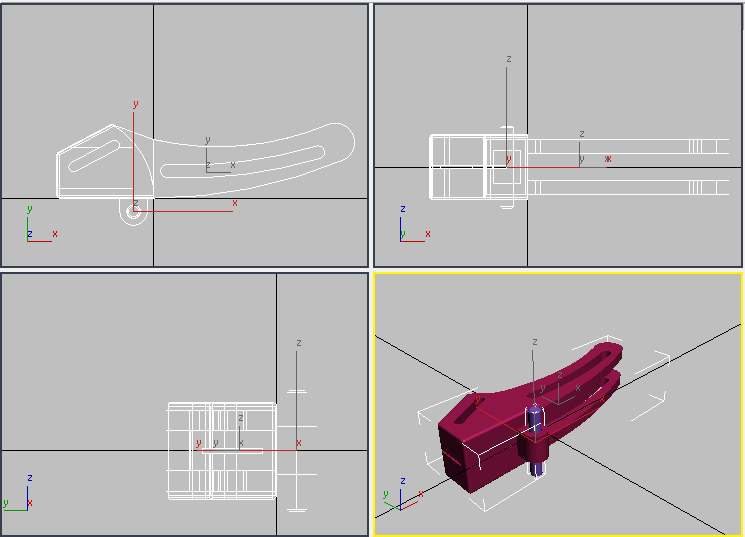
There are two objects: blade_clamp_01 is the mounting pin, and blade_clamp_02 is the clamp itself.
 Select the clamp, blade_clamp_02,
and go to the
Select the clamp, blade_clamp_02,
and go to the  Modify panel.
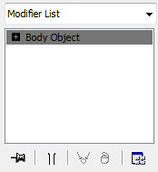
SAT objects appear in 3ds Max Design as the Body Object type. Body Objects model solids.
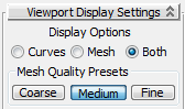
By default, the display is set to Both and Medium.
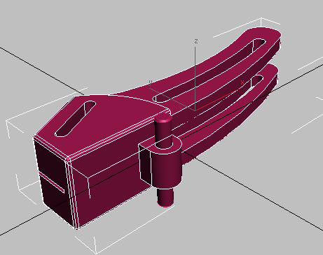
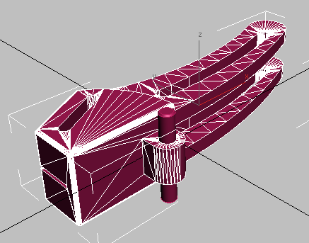
In viewports, 3ds Max Design approximates Body Objects as meshes. Try choosing Coarse and then Fine as the mesh types.
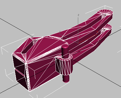
Coarse mesh
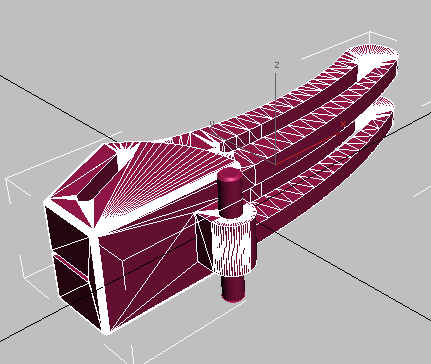
Fine mesh
If you plan to deform the Body Object geometry, as in this tutorial, then it helps to set the Max Edge Len[gth] % value explicitly.
3ds Max Design subdivides the mesh approximation.
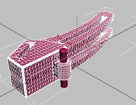
This fine-grained subdivision gives 3ds Max Design modifiers adequate geometry to modify.
When Max Edge Len. % is set to 0.0, the parameter is inactive. Values between 2.0 and 5.0 are good for deforming geometry in 3ds Max Design.