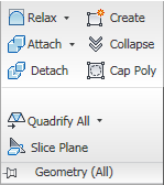
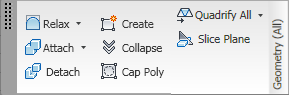
The Geometry (All) panel provides a subset of modeling tools from the Edit Geometry rollout and adds Cap Poly for creating a polygon from a vertex or edge selection and the Quadrify tools for converting polygons to quadrilaterals.
Geometry (All) panel on minimized ribbon

Geometry (All) panel on maximized ribbon, with expansion
Geometry (All) panel floating, with expansion
 Relax
Relax
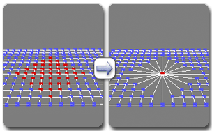
Applies the Relax function to the current selection, using the current Relax settings (see following). Relax normalizes mesh spacing by moving each vertex toward the average location of its neighbors. It works the same way as the Relax modifier.
At the object level, Relax applies to the entire object. At sub-object levels, Relax applies only to the current selection.
Opens the Relax caddy, which lets you specify how the Relax function is applied.
 Create
Lets you create new geometry. How this button behaves depends on which level is active:
While creating a polygon at the Polygon or Element level, you can delete the most recently added vertex by pressing Backspace. You can do this repeatedly to remove added vertices in reverse order of placement.
You can start creating polygons in any viewport, but all subsequent clicks must take place in the same viewport.
Edges you create separate the polygons. For example, by creating an edge inside a quadrilateral polygon, you turn it into two triangles.
 Attach
Lets you attach other objects in the scene to the selected poly object. After activating Attach, click an object to attach to the selected object. Attach remains active, so you can continue clicking objects to attach them. To exit, right-click in the active viewport or click the Attach button again.
You can attach any type of object, including splines, patch objects, and NURBS surfaces. Attaching a non-mesh object converts it to editable-poly format.
When you attach an object, the materials of the two objects are combined in the following way:
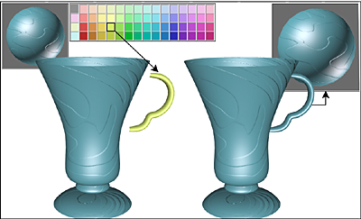
Handle inherits material from the cup it is being attached to.
Attach remains active in all sub-object levels, but always applies to objects.
Lets you attach other objects in the scene to the selected mesh. Click to open the Attach List dialog, which works like Select From Scene to let you choose multiple objects to attach.
 Collapse (Sub-object levels only)
 Detach (Sub-object levels only)
Separates the selected sub–objects and associated polygons as a new object or element(s).
When you click Detach, the software prompts you for the options specified on the Detach dialog. If the object is in Edit Poly (modifier) format, you can detach using the current settings without opening the dialog by Shift+clicking the Detach button.
 Cap Poly
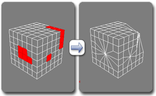
Creates a single polygon from a vertex or edge selection and selects the polygon. Available at the Vertex, Edge, and Border sub-object levels only.
Select vertices or edges and then click Cap Poly.

Using Cap Poly with a vertex selection
Using Cap Poly with an edge selection
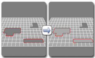
Using Cap Poly with a border selection
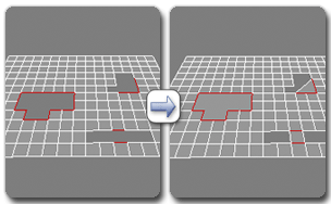
When capping an edge selection, the software uses the edge vertices to determine the feasibility of creating a polygon. When using Cap Poly at the Vertex or Edge level, the software requires a non-overlapping counter-clockwise sequence of selected sub-objects. Consider the example shown in the following illustration, in which the goal is to cap all border edges or vertices:
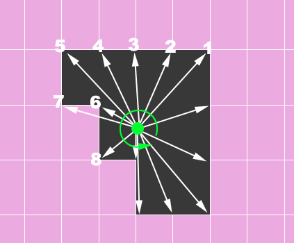
The software first determines the geometric center of the selected sub-objects (the small green disc), and then shoots out “rays” in counter-clockwise order from that location to find the locations of vertices from which to form a polygon. In this case, it finds vertex 6 before it finds vertex 7, but vertex 7 actually precedes vertex 6 when going around the border in counter-clockwise order. As a result, Cap Poly cannot form the polygon because the vertices it finds are in the wrong order.
In such cases, apply Cap Poly at the Border sub-object level.
A set of tools for converting triangles to quadrilaterals. Click the visible tool to apply it, or choose another tool from the drop-down list.
Creates a gizmo for a slice plane that you can position and rotate to specify where to slice. Also enables the Slice and Reset Plane buttons; click Slice to create new edges where the plane intersects the geometry.
If you use Slice Plane from the modeling ribbon, the Slice, Split, and Reset Plane controls are available on the Slice Mode contextual panel.
If snapping is off, you see a preview of the slice as you transform the slice plane. To perform the slice, click the Slice button.
The Slice Mode contextual panel is available on the modeling ribbon when the Slice Plane tool is active. It provides tools for performing the slice and resetting the slice plane position, as well as an option for splitting the mesh while slicing.