To edit a CAT spine, use the Spine Setup rollout on the Modify panel.
When you set a spine to be Procedural, the motion of all the spine bones is defined by an algorithm. The CAT spine algorithm always tries to bend the spine in a way that makes sense for that spine. The bend amount for each bone is defined by the Spine Curvature graph.
Benefits of using procedural spines include:

If you select a bone in a procedural spine and go to the Motion panel, you see a small Spine Motion rollout. The single slider on this rollout defines the Absolute/Relative behavior of the spine.
A Relative spine produces a smooth C-shaped curve, while an Absolute spine creates an S-shaped curve.

Left: Relative spine
Right: Absolute spine
When you rotate the tip hub of a Relative spine, the hub moves in an arc around the base of the spine.
You typically use a Relative spine when the curvature of the spine is more importnant than the exact locaion of the tip hub. This is why the default setting for necks in CAT is Relative. The position of the head is usually less important than the curvature of the neck.
When you rotate the tip hub on an Absolute spine, the hub stays approximately stationary.
Use an Absolute spine when the position of the ribcage is important. For example, with a quadruped, the ribcage position is usually more important than it is with a biped. This is because the front legs of the quadruped are usually on the ground, so the position of the ribcage defines how straight the legs are. In this situation, even a small movement of the ribcage can change the shape of the legs and the weighting of your character.
Of course, in CAT the Absolute Relative value is animatable, so you can specify throughout an animation how the spine should behave at any given moment. In many cases, you might need to animate the spine settings to get the desired results.
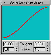
The Spine Curvature rollout settings control the extent to which spine links rotate relative to each other. In other words, it controls how the rotation between the hubs is distributed along the spine.
You edit the spline by adjusting the Tangent and Value settings at the bottom of the rollout.
By default, the spine bends evenly along its length. As you rotate the tip hub, the spine interpolates the rotation throughout the spine nodes according to the curvature of the graph.

Default graph settings
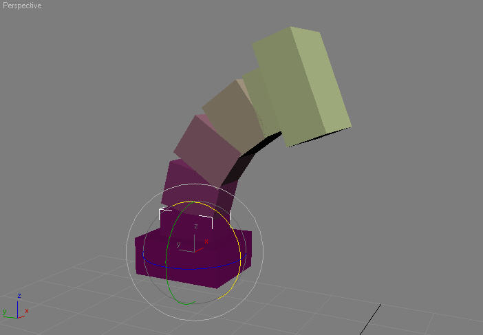
The default curvature is evenly distributed among the spine bones.
The following examples use a spine with the Absolute Relative value set to 1, meaning that it is a Relative spine.
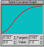
If you adjust the graph to be flatter at the start and bend up sharply at the end, then the spine will also bend sharply at the end.

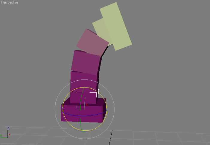
You can also configure the spine to bend more at its base.
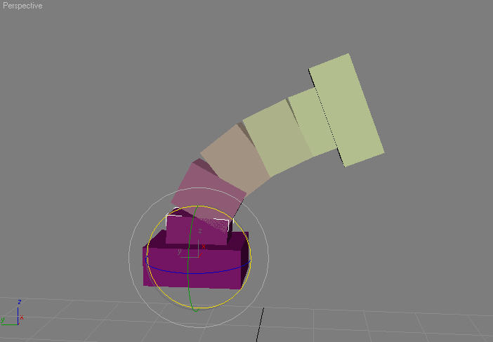
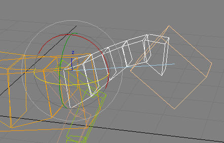
The Spine Direction vector is a line that determines the default direction for the spine. In other words, when the spine is at rest, it should project along this vector. By default, the Spine Direction vector points along the base hub’s length axis: Z for Z axis-aligned rigs and X for X-aligned rigs. See Understanding the Bone Length Axis.
You will get better results if you ensure that the blue line runs close to default curvature of the spine.
FK (keyframed) spines behave like a standard hierarchy of bones in CAT. Each bone has its own Layer controller for controlling its transform and can be keyframed independently, giving you precise control. You can then do things like dislocate spine bones by animating the positions.