Command entry:
Create panel


(Space Warps)
Particles & Dynamics
Object Type rollout
Vector Field
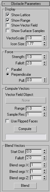
Obstacle Parameters rollout
Command entry:Select a Vector Field space warp.

Modify panel
Obstacle Parameters rollout
A vector field, generated around an obstacle object, allows crowd members to avoid that object in a scene. The field consists of a three-dimensional array of vectors which guide delegates
or other objects around the obstacle. The settings in this rollout help determine how the vectors are generated and displayed,
and how they affect other objects.
NoteObjects are subject to a vector field's forces only if they are bound to the field with a Crowd object. For general usage
guidelines, see
To use a Vector Field space warp.
Interface
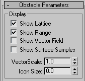
Display group
The check boxes in this group let you enable and disable display of four different elements of the Vector Field space warp.
NoteYou can select a Vector Field space warp in the viewport by clicking any of its visible elements except the range representation. If you've turned off display of all four elements, you can still select the space warp by clicking
its gizmo, which, when viewed from the "top" (the orthographic viewport in which the warp was created), resembles a pair of
crossed double-headed arrows in the shape of an X.
- Show Lattice
-
Displays the vector field lattice, a yellow wireframe box. Default=on.
The vectors are generated at lattice intersections inside the vector field range.
- Show Range
-
Displays the volume about the obstacle object within which vectors are generated, as an olive-colored wireframe. Default=on.
The range starts out the same shape and size as the obstacle object, and is typically enlarged with the Compute Vectors group
Range setting.
- Show Vector Field
-
Displays vectors, which appear as blue lines emanating outward from lattice intersections within the range volume. Default=off.
- Show Surface Samples
-
Displays short green lines emanating from sample points on the surface of the obstacle object. Default=off.
These appear only after you've computed the vector field. See Sample Resolution for more information.
- VectorScale
-
Scales the vectors so they're more visible or less obtrusive. Default=1.0.
NoteThis setting does not affect the strength of the vectors; only their visibility.
- Icon Size
-
Adjusts the size of the Vector Field space warp icon, a pair of crossed double-headed arrows. Increase the size for easier
viewport selection. Default=size originally drawn in viewport.
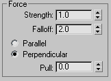
Force group
These parameters determine how the vector field affects objects within its volume.
Changing any of the Force group settings does not require that you recalculate the vector field.
NoteUsing a vector field does not guarantee that delegates or particles remain at a particular distance from the obstacle. In
some cases you might have to animate the Strength, Falloff, and/or Pull settings to keep delegates within the vector field.
- Strength
-
Sets the degree of effect the vectors have on the movement of an object entering the vector field. If Show Vector Field is on as you adjust Strength, you can see the vector lines change size in the viewports in real time. Default=1.0.
NoteSometimes, after changing strength, vectors will be too large or too small. In such cases, adjust the
VectorScale parameter so that they display properly.
- Falloff
-
Determines the rate at which the strength of the vectors falls off with distance from the surface of the object. Default=2.0.
A value of 0 will make all the vectors the same size. A value greater than 0 will make them get smaller as they get farther
away from the object surface. A value less then 0 will make them get larger as they get farther away.
- Parallel/Perpendicular
-
Sets whether the force generated by the vectors works parallel or perpendicular to the vector field. Default=Perpendicular.
Because the vectors are perpendicular to the object surface, and you typically would want delegates to travel parallel to
the surface, you would normally use a perpendicular force.
- Pull
-
Adjusts objects' position relative to the field. Available only when Perpendicular is chosen. Default=0.0. Range=-1.0 to 1.0.
Objects moving perpendicular to a vector field sometimes tend to drift away from it, due to lack of subsampling. The Pull
parameter helps to pull objects back. Pull values greater than 0 create a pulling force towards the source of the vector field
vector. Values less than 0 pull the force towards the direction in which the vector field's vector is pointing. A value of
0.0 produces a force perfectly perpendicular to the vector field's vector.
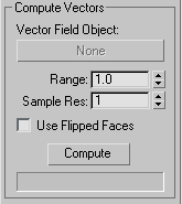
Compute Vectors group
- Vector Field Object
-
Lets you designate the obstacle object. Click this button, and then select the object around which the vector field is to
be generated. Thereafter the object's name appears on the button (which is intially labeled “None”).
NoteYou can only use primitives and unmodified editable mesh objects as obstacles. Also, the object should be fully enclosed in
the Vector Field lattice.
- Range
-
Determines the volume within which vectors are generated. Default=1.0.
The range is represented in viewports as an olive-colored wireframe that starts out the same size and shape as the obstacle
object. Increasing the Range setting moves the wireframe away from the obstacle object in the direction of its surface normals.
In crowd simulations, the Range outline is where the delegates start to "see" the obstacle object, and begin to turn to avoid
it. If your crowd members are penetrating the obstacle, or even just coming too close to it before turning, increase the Range
setting. Also try increasing the Vector Field lattice resolution and/or the Sample Res setting.
- Sample Res(olution)
-
Acts as a multiplier of the effective sampling rate used on the obstacle object's surface to calculate vector directions in
the field. Default=1.
The basic sampling rate is determined by 3ds Max from the size of the lattice and the size of each polygon.
- Use Flipped Faces
-
Causes flipped normals to be used during the computation of the vector field. Default=off.
By default, vectors are generated in the same direction as the obstacle object's face normals, so that assuming these face
normals point outward, objects move around its exterior in a crowd simulation. However, if you want objects to remain within
an object's interior, turn on Use Flipped Faces.
TipIf you run a crowd simulation inside an object that is also being viewed from the inside, such as a room, you'll probably
want the object's faces to point inward. In that case, use Editable Mesh/Edit Mesh
Surface Properties to flip the normals, and don't turn on Use Flipped Faces.
- Compute
-
Calculates the vector field.
Always recalculate the vector field after changing any parameters except those in the Force group.
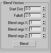
Blend Vectors group
Use the Blend Vectors parameters to reduce abrupt changes in the angles of neighboring vectors. For example, if you have a
wavy surface, you might get wavy vectors very far out from the surface, which could adversely affect the simulation. Use Blend
Vectors to correct this condition.
- Start Dist
-
The distance from the object at which you want to start blending the vectors. Default=0.0.
- Falloff
-
The falloff of the blend of the surrounding vectors. Default=2.0.
- Blend segs X
-
The number of adjacent lattice points to blend on the X axis. Default=1.
- Blend segs Y
-
The number of adjacent lattice points to blend on the Y axis. Default=1.
- Blend segs Z
-
The number of adjacent lattice points to blend on the Z axis. Default=1.
- Blend
-
Click this button to implement the blending.