


An edge is a line connecting two vertices that forms the side of a polygon. An edge can't be shared by more than two polygons. Also, the normals of the two polygons should be adjacent. If they aren't, you wind up with two edges that share vertices.
At the editable poly Edge sub-object level, you can select single and multiple edges and transform them using standard methods.
 Extrude
Lets you extrude edges manually via direct manipulation in the viewport. Click this button, and then drag vertically on any edge to extrude it.
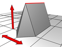
When extruding a vertex or edge interactively in the viewport, you set the extrusion height by moving the mouse vertically and the base width by moving the mouse horizontally.
Extruding an edge moves it along a normal and creates new polygons that form the sides of the extrusion, connecting the edge to the object. The extrusion has either three or four sides; three if the edge was on a border, or four if it was shared by two polygons. As you increase the length of the extrusion, the base increases in size, to the extent of the vertices adjacent to the extruded edge's endpoints.
Following are important aspects of edge extrusion:
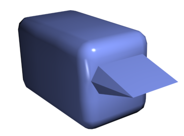
Chamfer box showing extruded edge
Opens the Extrude Edges caddy, which lets you perform extrusion via interactive manipulation.
If you click this button after performing a manual extrusion, the same extrusion is performed on the current selection as a preview and the caddy opens with Extrusion Height set to the amount of the last manual extrusion.
 Chamfer
Click this button and then drag edges in the active object. To chamfer edges numerically, click the Chamfer Settings button and change the Chamfer Amount value.
If you chamfer multiple selected edges, all of them are chamfered identically. If you drag an unselected edge, any selected edges are first deselected.
An edge chamfer "chops off" the selected edges, creating a new polygon connecting new points on all visible edges leading to the original vertex. The new edges are exactly <chamfer amount> distance from the original edge along each of these edges. New chamfer faces are created with the material ID of one of the neighboring faces (picked at random) and a smoothing group which is an intersection of all neighboring smoothing groups.
For example, if you chamfer one edge of a box, each corner vertex is replaced by two vertices moving along the visible edges that lead to the corner. Outside faces are rearranged and split to use these new vertices, and a new polygon is created at the corner.
Using Chamfer at the Edge level
Alternatively, you can create open space around the chamfered edges; for details, see Chamfer.
Opens the Chamfer caddy, which lets you chamfer edges via interactive manipulation and toggle the Open option.
If you click this button after performing a manual chamfer, the same chamfer is performed on the current selection as a preview and the caddy opens with Chamfer Amount set to the amount of the last manual chamfer.
 Weld
Weld
Combines selected edges that fall within the threshold specified on the Weld caddy.
You can weld only edges that have one polygon attached; that is, edges on a border. Also, you cannot perform a weld operation that would result in illegal geometry (e.g., an edge shared by more than two polygons). For example, you cannot weld opposite edges on the border of a box that has a side removed.
Opens the Weld Edges caddy, which lets you specify the weld threshold.
 Bridge
Connects border edges on an object with a polygon “bridge.” Bridge connects only border edges; that is, edges that have a polygon on only one side. This tool is particularly useful when creating edge loops or profiles.
There are two ways to use Bridge in Direct Manipulation mode (that is, without opening the Bridge Edges caddy):
The new polygons that result from a Bridge operation are automatically selected; you can see this by accessing the Polygon sub-object level.
Using Bridge at the Edge level
Opens the Bridge Edges caddy, which lets you add polygons between pairs of edges via interactive manipulation.
 Remove
Deletes selected edges and combines the polygons that use them.
Removing one edge is like making it invisible. The mesh is affected only when all or all but one of the edges depending on one vertex are removed. At that point, the vertex itself is deleted and the surface is retriangulated.
To delete the associated vertices when you remove edges, press and hold Ctrl while executing a Remove operation, either by mouse or with the Backspace key. This option, called Clean Remove, ensures that the remaining polygons are planar.
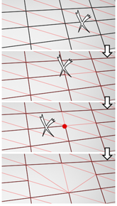
Left: The original edge selection
Center: Standard Remove operation leaves extra vertices.
Right: Clean Remove with Ctrl+Remove deletes the extra vertices.
Edges with the same polygon on both sides usually can't be removed.
 Split
Split
Divides the mesh along the selected edges.
This does nothing when applied to a single edge in the middle of a mesh. The vertices at the end of affected edges must be separable in order for this option to work. For example, it would work on a single edge that intersects an existing border, since the border vertex can be split in two. Additionally, two adjacent edges could be split in the middle of a grid or sphere, since the shared vertex can be split.
 Target Weld
Allows you to select an edge and weld it to a target edge. When positioned over an edge, the cursor changes to a + cursor. Click and move the mouse and a dashed line appears from the vertex with an arrow cursor at the other end of the line. Position the cursor over another edge and when the + cursor appears again, click the mouse. The first edge is moved to the position of the second, and the two are welded.
You can weld only edges that have one polygon attached; that is, edges on a border. Also, you cannot perform a weld operation that would result in illegal geometry (e.g., an edge shared by more than two polygons). For example, you cannot weld opposite edges on the border of a box that has a side removed.
 Spin
Spin
 Insert Vertices
 Create Shape From Selection
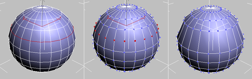
After selecting one or more edges, click this button to create a spline shape from the selected edges. A Create Shape dialog appears, letting you name the shape and set it to Smooth or Linear. The new shape's pivot is placed at the center of the poly object.
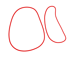
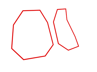
An edge selection (top); a smooth shape (center); a linear shape (bottom)
Sets the weight of selected edges. Used by the NURMS subdivision option and by the MeshSmooth modifier.
Increasing an edge weight tends to push the smoothed result away.
 .
.
For instructions for using the caddy, see The Caddy Interface.
Toggles the availability of the Weight control on the The Caddy Interface when Select And Manipulate is active.
Specifies how much creasing is performed on the selected edge or edges. Used by the NURMS subdivision option and by the MeshSmooth modifier.
At low settings, the edge is relatively smooth. At higher settings, the crease becomes increasingly visible. At 1.0, the highest setting, the edge becomes a hard crease.
 .
.
For instructions for using the caddy, see The Caddy Interface.
Toggles the availability of the Crease control on the The Caddy Interface when Select And Manipulate is active.

