In this lesson, you will create another reference object and apply additional polygon editing techniques that will cloak the building in a metallic shell.
 open \modeling\highrise\building1_mullions.max.
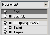
You will start by temporarily deactivating the modifiers on the glazing object, so you can work with the polygons of the shell object more easily.
Create a metallic shell for the building:
 Modify Panel, in the modifier stack, click the
  (light-bulb icon) to the left of each modifier to turn off the effect of the modifier.
 Clone. In the Clone Options dialog Object group, choose Reference and change the name of the object to Building 1 - Metallic Shell.
 Zoom,
Zoom,  orbit, and
  pan until the bottom of the building is clearly visible.
 (Polygon) to turn it on.
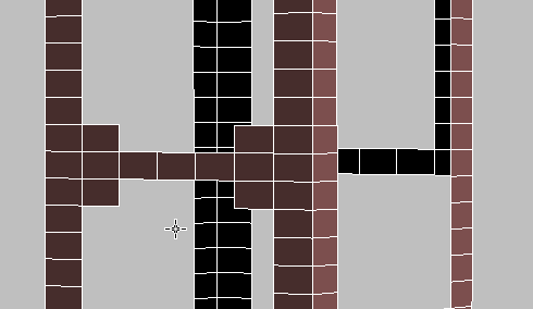
 Select the middle polygon on the bottom of the building. On the Selection rollout, click Grow repeatedly until you have the
entire bottom selected. Press Delete to remove the polygons.
Select the middle polygon on the bottom of the building. On the Selection rollout, click Grow repeatedly until you have the
entire bottom selected. Press Delete to remove the polygons.
You now need to remove additional polygons to create the window pattern on the building exterior.
Create openings for the front and back of the building shell:
 Show The ViewCube.
You will be selecting faces on both the front and back of the building, and this is more reliable in Orthographic views. (In a Perspective view, the Perspective projection can cause selection to choose back faces that are out of alignment with the front.)
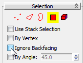
While Ignore Backfacing is off, selecting a face on the front of the building also selects the corresponding face on the back.
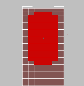
 (Select Object). Ctrl+click+drag to select a 5x15 grid of polygons in the upper portion of the model, leaving one row of polygons unselected at
each edge of the building.
(Select Object). Ctrl+click+drag to select a 5x15 grid of polygons in the upper portion of the model, leaving one row of polygons unselected at
each edge of the building. 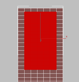
This selects polygons on both the front and back faces of the model.

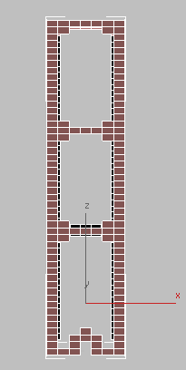
Next, you will remove polygons from the sides of the building, using a slightly different pattern.
Create openings for the sides of the building shell:


Next, you will edit the building edges to make them rounded.
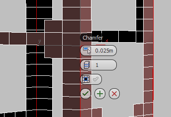
Chamfer the corners of the shell:
 (Edge).
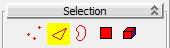
 click and Ctrl+click to select the four vertical edges at each corner of the building.
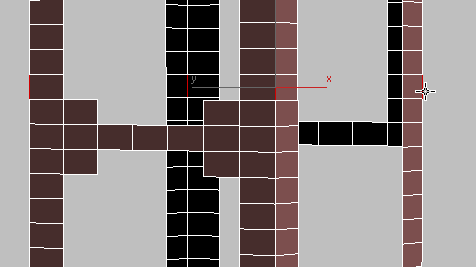
 Settings button next to the Chamfer button (just to the right of the main button).
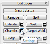
3ds Max Design displays the caddy controls for the Chamfer tool.
 (OK).
(OK). 
 (Edge) again to exit the Edge sub-object level.
Give thickness to the shell, and inspect the result:
 (Zoom Extents Selected).
Click an empty area of the viewport to deselect the building.
(Zoom Extents Selected).
Click an empty area of the viewport to deselect the building.
The modeling phase of the building is now complete. Next, you will add materials to the building exterior.
Apply materials to the building:

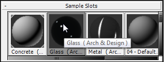
 (Material Editor) to open the Slate Material Editor.
(The View, initially labeled View1, is the large window in the center of the Slate Material Editor where materials and maps appear as nodes that you can wire together in various ways.)
3ds Max Design asks whether to make this a copy or an instance. Choose Instance, then click OK.
 (Assign Material To Selection) to apply the Glass material to the glazing object.
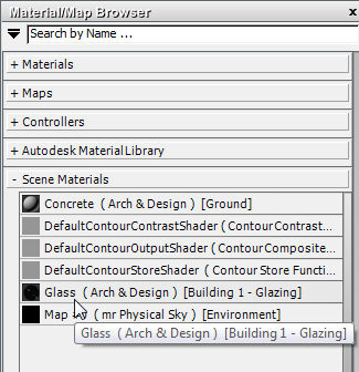
3ds Max Design applies the glazing material to the glazing. In the Scene Materials section of the Browser panel, now you can see a Glass entry, and the object name.
This removes the Glass material from the active material view, but doesn’t remove it from the scene.

Dragging from a material’s output socket
... and in the viewport, drop the wire on the metal shell object.

... and dropping onto an object
The Mullions material is a matte gray, not shiny like the metallic shell.
 Close the Slate Material Editor.
 (Render Production) to check your work.
Your scene should look something like this:
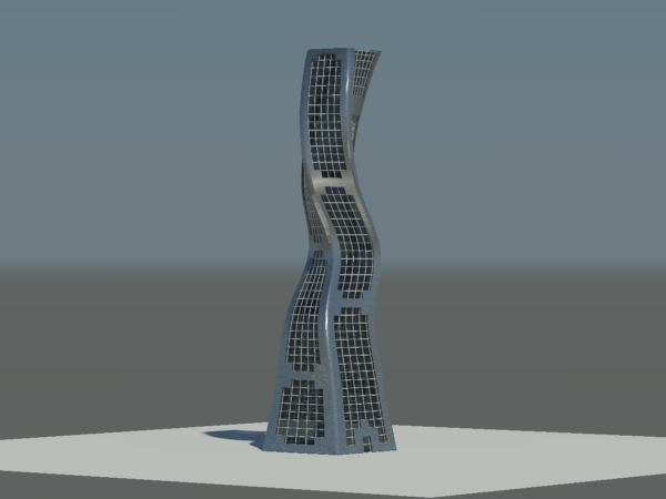
You can use this scene file as your starting point in the next tutorial, Modeling Buildings Using Boolean Operations.
This tutorial demonstrated how easy it is to quickly visualize architectural concepts using 3ds Max Design. You learned how to build an organically-themed architectural model from simple geometric objects by adding Twist, Taper, and FFD modifiers. You also saw how basic polygon editing techniques can be used to create detailed elements such as mullions, and to round off building corners.


