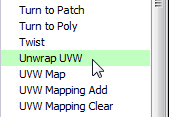
As for Facade1, you use Unwrap UVW to texture the entryway faces of Facade4. Because of the arrangement of these faces, you use different Unwrap UVW techniques.
 open \modeling\facades\facade_modeling_05.max.
 select the façade, go to
the
select the façade, go to
the  Modify panel, and make sure
that
Modify panel, and make sure
that  (Show End Result) is on
for all three levels of the stack.
Select Facade4.
(Show End Result) is on
for all three levels of the stack.
Select Facade4.
 Orbit (or use the ViewCube),
  zoom, and
  pan to get a good view of
the arch geometry.
pan to get a good view of
the arch geometry.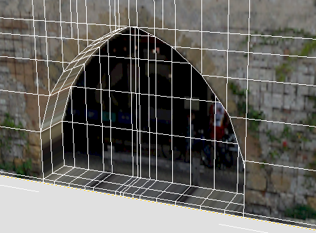
Modify panel. In the modifier
stack, make sure UVW Mapping is the active level.
 (the plus-sign icon) by the
Unwrap UVW entry to expand the Unwrap UVW sub-levels, then click the
Face sub-object level to make it active.
(the plus-sign icon) by the
Unwrap UVW entry to expand the Unwrap UVW sub-levels, then click the
Face sub-object level to make it active.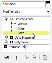
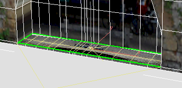
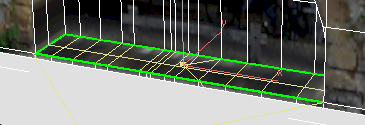
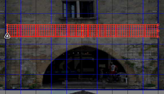
Click and Ctrl+click to select the upper faces
of the doorstep or sidewalk.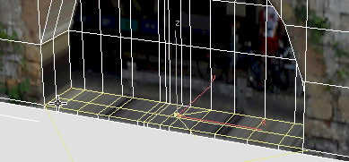
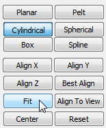
Modify panel  Map Parameters rollout,
click to turn on Planar, then click Align Z.
Map Parameters rollout,
click to turn on Planar, then click Align Z.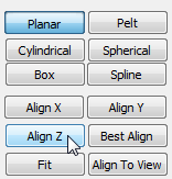
Now the pavement is correctly aligned with the fac4.jpg texture.
Modify panel Parameters rollout,
click Edit to open the Edit UVWs dialog.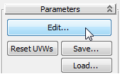

 (Filter Selected Faces).
 (Freeform Mode).
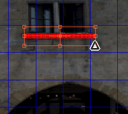
The idea is to map the pavement to a dark area of stone.
 Close the Edit UVWs dialog.
Set up texturing for the wall portion of the arch:
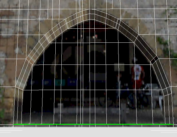
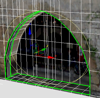
Click and Ctrl+click to select the outer faces
along the inside of the archway: These are the faces that correspond
to the width of the stone wall.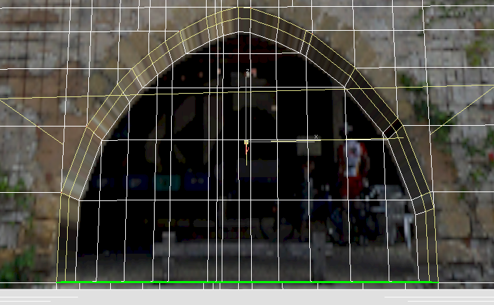
Modify panel Map Parameters rollout,
click Cylindrical to turn it on, then click Align Y.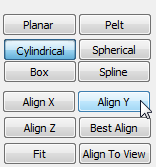
3ds Max displays a cylindrical gizmo for the Unwrap UVW projection.
 Move the cylinder gizmo
forward a bit, so you can see all of it, and it is not hidden by
the wall.
Move the cylinder gizmo
forward a bit, so you can see all of it, and it is not hidden by
the wall.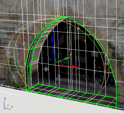
orbit (or use the ViewCube)
to see the wall and the cylinder gizmo more obliquely.
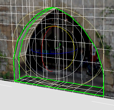
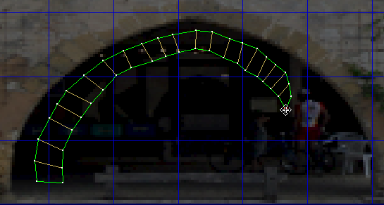
The cylinder gizmo has one height segment displayed in green. This indicates where the seam of the cylindrical mapping will be. At present, the green segment is near the right side of the arch.
 (Select And Rotate).
 Rotate the cylinder gizmo
about the Y-axis until the seam segment is at the bottom of the
scene.
Rotate the cylinder gizmo
about the Y-axis until the seam segment is at the bottom of the
scene.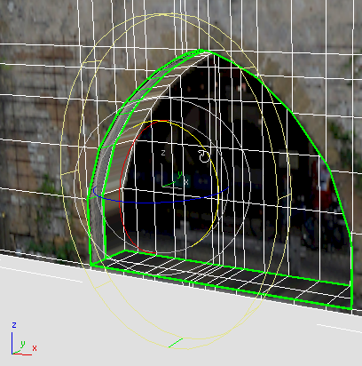
Since the arch isn’t a full circle, putting the seam at the bottom ensures there won’t be a seam on the façade geometry.
3ds Max fits the cylinder gizmo to the geometry of the arch.
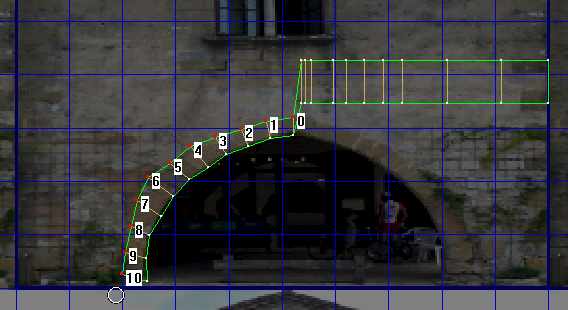
Use the Edit UVWs dialog to position the wall texture:
Modify panel Parameters rollout,
click Edit to display the Edit UVWs dialog.
(Filter Selected Faces).
(Freeform Mode).
 (Mirror Horizontal).
 (Vertex Sub-Object Mode).
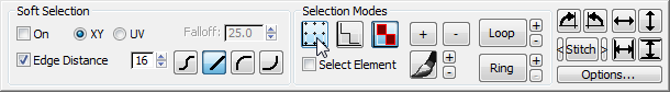
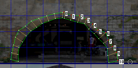
Sketch
Vertices.
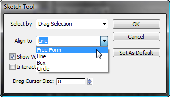
Also in the Sketch Tool dialog, click to turn on Interactive Mode, and then click OK.
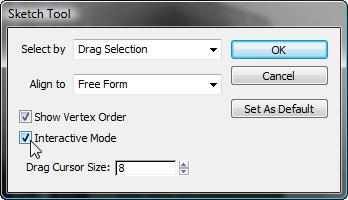
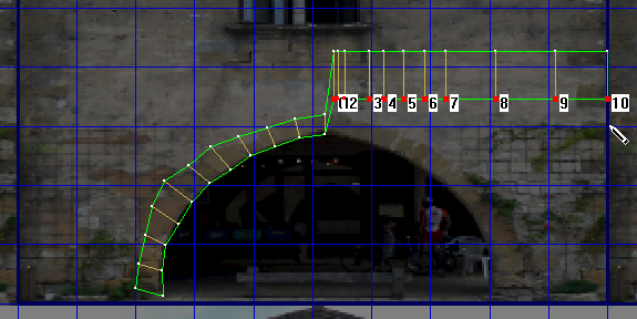
After you have set up the Sketch Tool to use Free Form drawing, you work in a two-step manner: First, drag to select the vertices you want to reposition; Second, draw a freehand stroke to show Edit UVWs where to place the selected vertices.
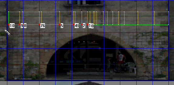
3ds Max moves the vertices you selected to follow the line as you draw.
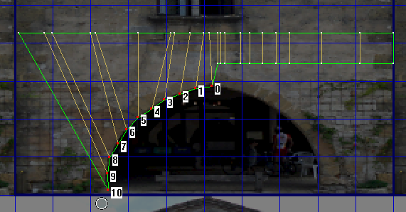
You don’t have to worry about being too precise: You can adjust your work later.
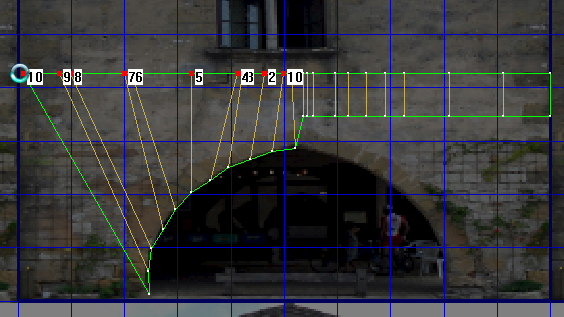
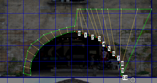
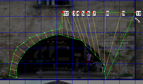
 (Move), and then move vertices
to arrange them more regularly.
(Move), and then move vertices
to arrange them more regularly.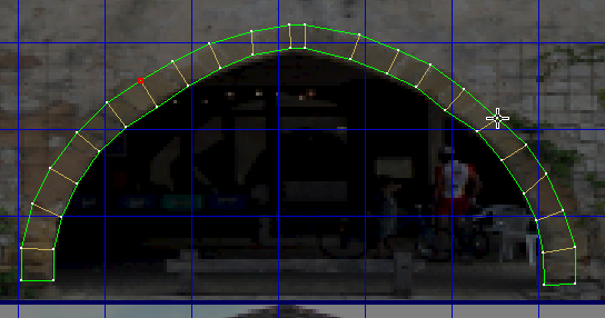
We’ll let you decide whether you want to go through the steps for mapping the inner, arcade faces. The steps to follow are the just same as the steps you followed for the stone wall faces, with these changes:
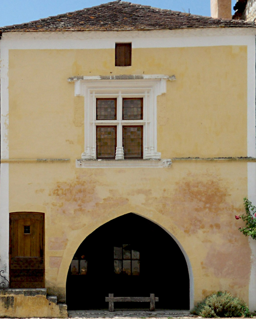
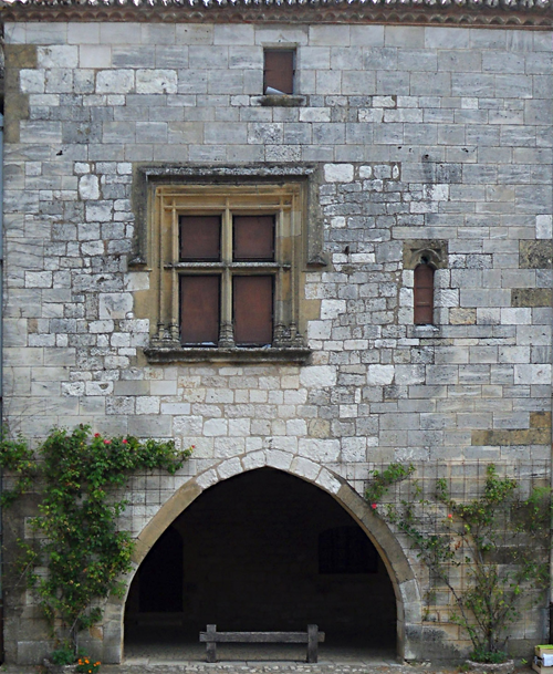
A close-up rendering of the façade shows the result of mapping the arch.
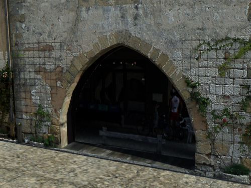
The completed scene is facade_modeling_completed.max. This scene contains two other façades. If you want to try modeling them, you should now know the tools you can use to do so.
Façade 2
Façade3
With a photograph of a building’s façade, you can create a convincing model of that façade. The overall steps are as follows:


