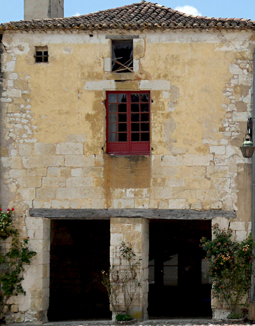
The first house, which we will call Facade1, is based on a single photograph, adjusted in the way described in Some Pointers: Preparing a Photo Before You Use It to Build a Model. In this lesson, you take several steps to set up the scene and the modifier stack, so that modeling will go more easily when you add detail to the façade.
The house begins as a simple plane.
 (Open File), navigate to
the \scenes\modeling\facades folder,
and open facade_modeling_start.max.
(Open File), navigate to
the \scenes\modeling\facades folder,
and open facade_modeling_start.max.The scene contains a plane to model the pavement, a Daylight system with a sky dome, and a few cameras that are hidden.
Optimize bitmap display in viewports:
 Preferences.
Configure
Driver.
Preferences.
Configure
Driver.
3ds Max opens the configuration dialog for the graphics driver you are using (Software, OpenGL, or Direct3D).
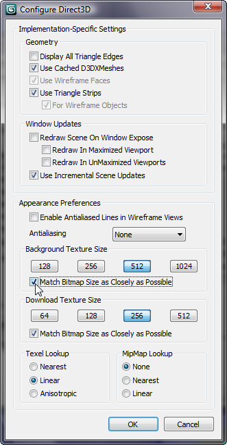
Configuration dialog for the Direct3D driver
Bitmap configuration changes do not take effect immediately: You always have to restart 3ds Max.
If you did not have to change the Match Bitmap Size setting, you can continue without restarting 3ds Max.
Make sure Use Real-World Texture Coordinates is turned off:
Preferences.
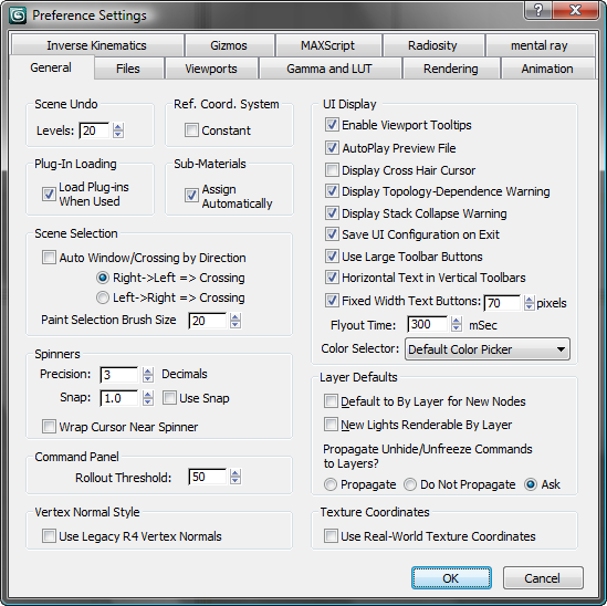
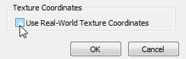
The dimensions of the scene will actually be close to the real-world dimensions, but 3ds Max doesn’t need to enforce that: This option would just add complications to your work.
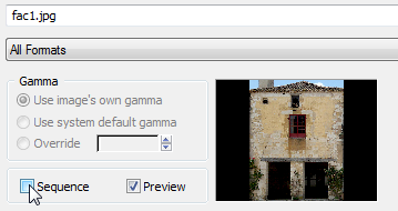
View the reference/texture bitmap, and note its dimensions:
View Image File. In
the View File dialog, navigate to the \sceneassets\images folder,
and highlight fac1.jpg.
In the lower-left corner of the View File dialog, a status line shows the dimensions of the image, which are 1200 x 1533 pixels. This will become the aspect ratio of the façade.

 Close the image window after
you have looked at the photo.
Close the image window after
you have looked at the photo.
Construct the plane that will become the façade:
 Create panel, click
  (Geometry) active, then
on the Object Type rollout, click Plane.
(Geometry) active, then
on the Object Type rollout, click Plane.
These dimensions roughly correspond to the aspect ratio of the photo: 1533:1200 pixels, or 0.78.
(After you convert the plane to an Editable Poly surface, you will subdivide it by using the polygon tools.)
 Hierarchy panel. On the
Adjust Pivot rollout, turn on Affect Pivot Only, then
Hierarchy panel. On the
Adjust Pivot rollout, turn on Affect Pivot Only, then  move the pivot vertically so
it is at the base of the Facade1 plane.
move the pivot vertically so
it is at the base of the Facade1 plane.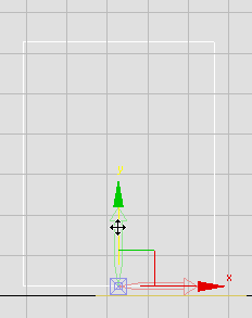
Pivot moved to the base of the plane
(Select And Move) still
active, on the status bar, right-click the X, Y, and Z spinner arrows
so the pivot of the plane is now located at the origin (0,0,0).
Setting the Z axis to 0.0 aligns the façade with the Ground object. Setting X and Y to 0.0 simply makes navigation easier, while you are editing the plane.
Convert
To Editable Poly.
 Open the Slate Material
Editor.
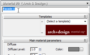
mental
ray, then drag the Arch & Design entry to the active View (the
large panel labeled View1 in the center of the Editor).
Open the Slate Material
Editor.
mental
ray, then drag the Arch & Design entry to the active View (the
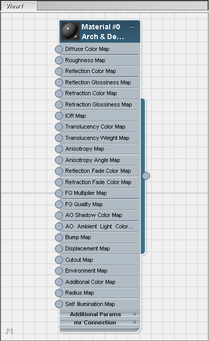
large panel labeled View1 in the center of the Editor).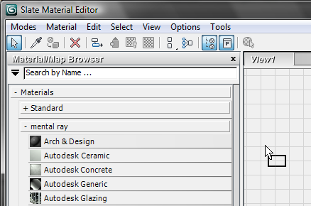
3ds Max displays the Arch & Design material node in the active View.
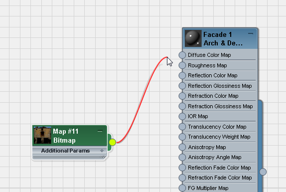
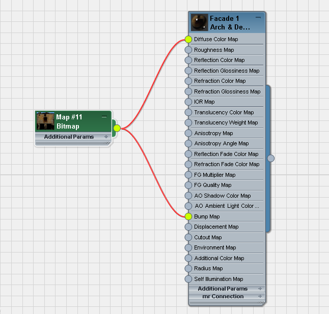
Standard, and drag the
Bitmap entry into the active View.
 (Assign Material To Selection),
and then turn on
(Assign Material To Selection),
and then turn on  (Show Map In Viewport).
Close the Slate Material
Editor.
(Show Map In Viewport).
Close the Slate Material
Editor.
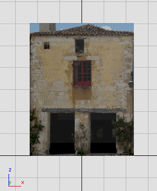
Shaded plane in Front viewport
Set Up the Stack so 3ds Max Preserves the Photo Projection
You are almost ready to add detail to the façade. But first, you need to set up 3ds Max so it displays the façade texture consistently, without distortion, and so it clearly highlights selected polygons.
open \modeling\facades\facade_modeling_01.max.
The goal of the steps
in this section is to be able to edit the Facade1 poly
surface without distorting the texture projected onto it. Editable
Poly objects have a toggle, Edit Geometry rollout Preserve UVs, that does a good job of preserving the
projection in most cases.
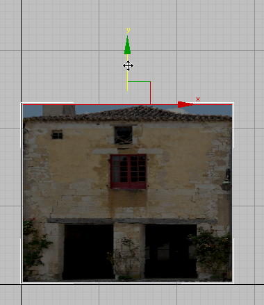
Moving an edge while Preserve UVs is off
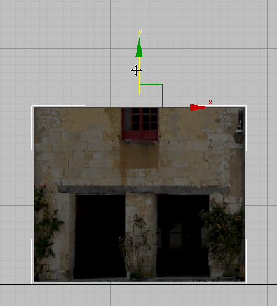
Moving an edge while Preserve UVs is on
The stack setup used in this section is an alternative method that works for surfaces other than Editable Poly.
 Select Facade1, then
go to the
Select Facade1, then
go to the  Modify panel.
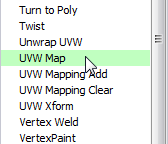
The UVW Map modifier has no visible effect: It merely provides more explicit mapping control than the implicit mapping provided by the Facade1 object’s texture coordinates.
 (Show End Result On/Off
Toggle) is on.
(Show End Result On/Off
Toggle) is on.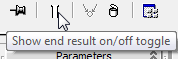
(Show End Result) is on
for Poly Select as well.
(Show End Result On/Off
Toggle) is on for the Editable Poly object (Facade1) as
well as for the modifiers.
Turning on Show End Result for all three levels of the stack causes the viewports to always display the full bitmap in its final placement, even while you edit the underlying geometry.
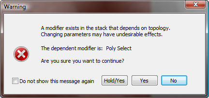
For the edits you are doing in this tutorial, it is safe to click Yes and proceed with your work. You also have the choice of turning on Do Not Show This Message Again before you click Yes: That disables display of this warning, but it does so not only for this tutorial, but for all future 3ds Max sessions. The choice is up to you, but for the remainder of this tutorial, we won’t mention the warning dialog again.
Now you have set up the stack so you can see the undistorted bitmap projection, even while you edit the geometry of Facade1.
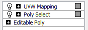
Stack setup for editing a poly surface with a bitmap
Show End Result must be on for all three levels.
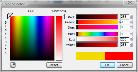
One further adjustment corrects for the situation that highlighted polys are hard to see with the default color scheme.
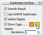
Change the color of selected faces:
Modify panel, with the Editable
Poly level active in the stack, scroll down to the Subdivision Surface
rollout, and open it if it isn’t already open.
In the next lesson, you will turn Facade1 into a three-dimensional façade.