The main fuselage is an extension of the cowl geometry.
Build the forward part of the fuselage from the rear of the cowl:
 Polygon Modeling panel, click
  (Polygon). In the Perspective
viewport,
(Polygon). In the Perspective
viewport,  click the polygon at the
rear of the cowl to select it.
click the polygon at the
rear of the cowl to select it.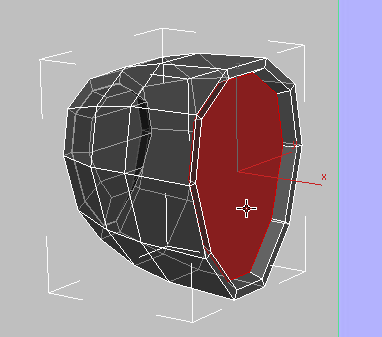
Polygons panel, click  (Inset). In the Perspective
viewport, drag downward to create an inset with very narrow border
polygons.
(Inset). In the Perspective
viewport, drag downward to create an inset with very narrow border
polygons.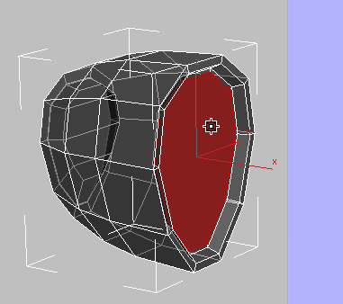
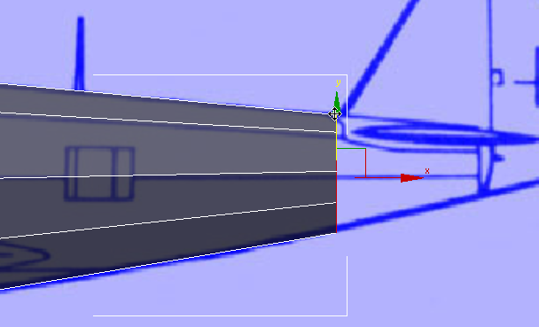
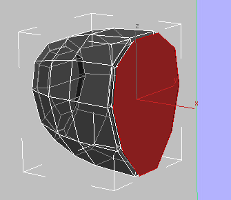
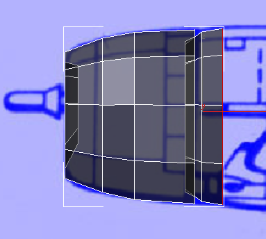
Polygons panel, click  (Bevel). In the Perspective
viewport, drag upward this time to extrude the polygon toward the
rear of the airplane. Watch the Front viewport while youre doing
so, and extrude the polygon just beyond the area of the cowl.
(Bevel). In the Perspective
viewport, drag upward this time to extrude the polygon toward the
rear of the airplane. Watch the Front viewport while youre doing
so, and extrude the polygon just beyond the area of the cowl.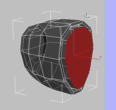
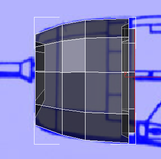
Front view
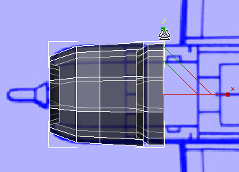
Release the mouse, then drag upward again to scale the bevel so it is almost the same diameter as the cowl itself. Again, watch the Front viewport while you work.
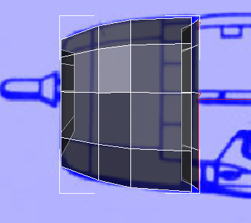
Front view
Continue modeling the fuselage:
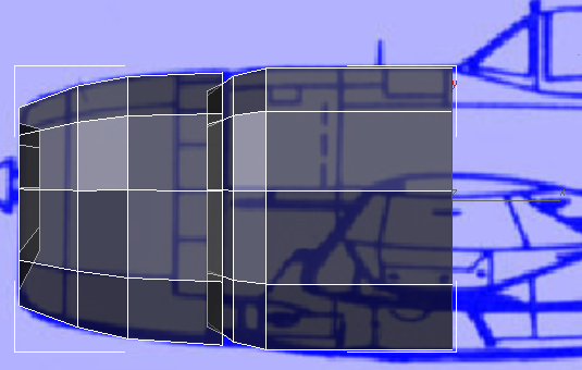
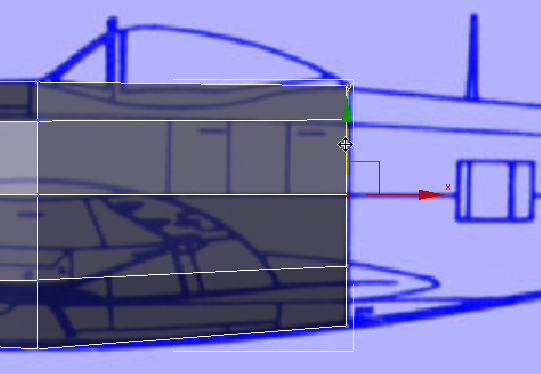
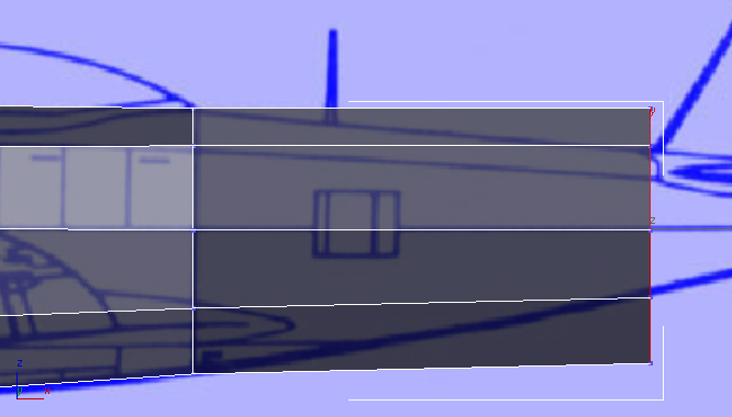
(Bevel) again to extend
the fuselage up to the leading edge of the rectangular panel in
front of the cockpit, then scale it up so that in the Front view,
it follows the contour of the blueprint image.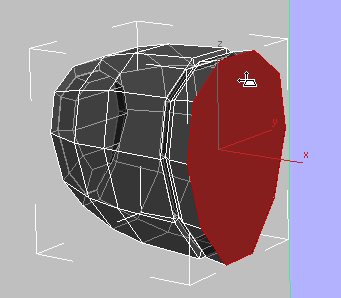
Front view
This looks good, but if you look at the Top viewport, you can see that the new bevel is a bit too wide.
From here on, Extrude is the main tool for creating the fuselage. Along the way, you will use Scale and vertex adjustments to refine its shape.
 pan the Front viewport so
you can see the cockpit.
Polygons panel, click
pan the Front viewport so
you can see the cockpit.
Polygons panel, click  (Extrude). In the Perspective
view, extrude the fuselage up to the leading edge of the cockpit.
As usual, watch the Front viewport while you work.
(Extrude). In the Perspective
view, extrude the fuselage up to the leading edge of the cockpit.
As usual, watch the Front viewport while you work.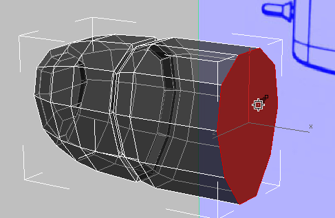
Front view
Polygon Modeling panel, click  (Vertex).
drag a box to select the
vertices at the lower edge of the rear of the fuselage. Then
(Vertex).
drag a box to select the
vertices at the lower edge of the rear of the fuselage. Then  move these vertices downward
along the Y axis to match the lower contour of the airplane.
move these vertices downward
along the Y axis to match the lower contour of the airplane.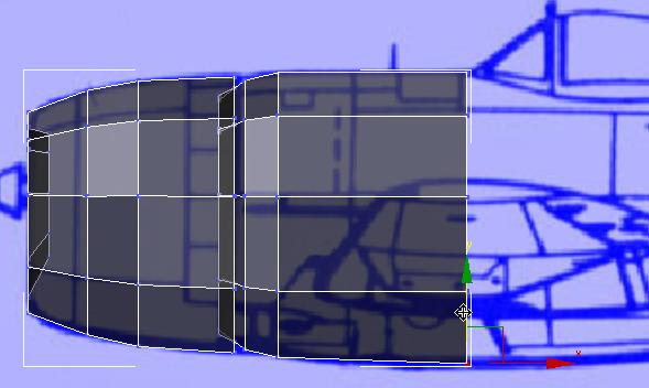
Polygon Modeling panel, click (Polygon) to return to the
Polygon sub-object level.
 scale the polygon down very
slightly along the Y axis.
scale the polygon down very
slightly along the Y axis.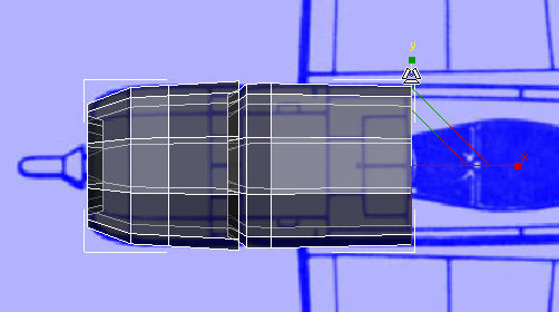
Polygons panel, click (Extrude) once more. Working
in the Perspective viewport, but watching the Front viewport, extrude
the fuselage as far as the seam at the rear of the cockpit.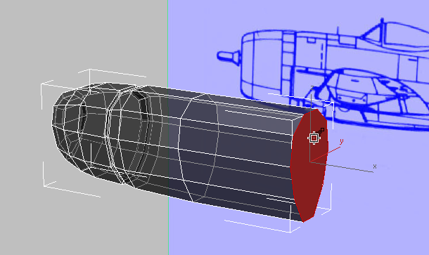
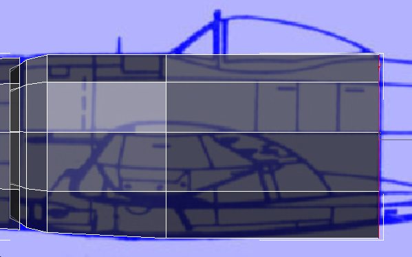
Front view
move the polygon up a bit along
the Y axis so the bottom is closer to the contour of the airplane.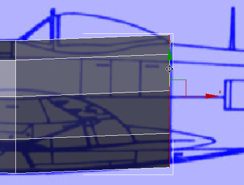
scale the polygon down along
the Y axis so it better matches the blueprint.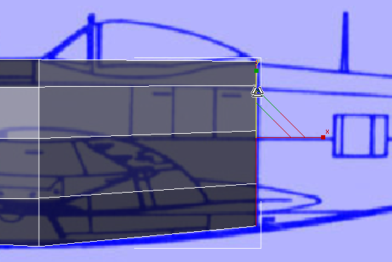
At this point, you might
also want to go to the (Vertex) sub-object level
and move the middle and lower
vertices so they better match the contours of the airplane. Remember
to use region selection so you select the vertices on both sides
of the fuselage.
After you adjust vertices,
return to the (Polygon) sub-object level.
scale the polygon down some more
along the Y axis, to match the blueprint image.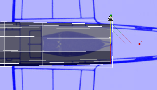
Complete the cylindrical part of the fuselage:
Polygons panel, click (Extrude) once more. Then
extrude the fuselage as far as the leading edge of the tail.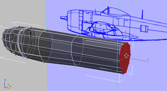
Front view
scale the polygon down to match
the contour of the airplane.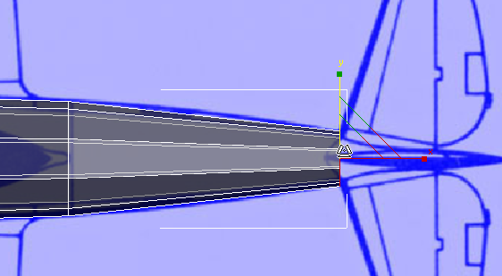
scale the polygon down to the
size of the contour.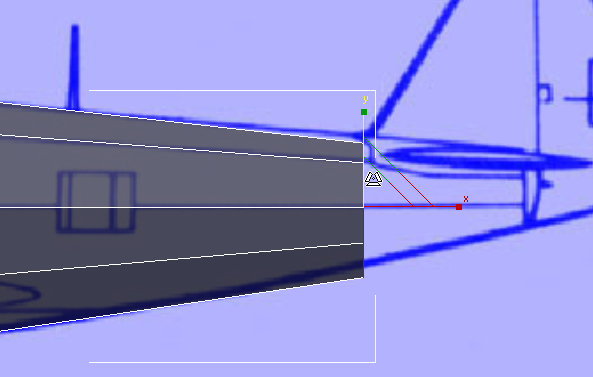
move the polygon to better
match the blueprint image.