Complete the Lower Part
of the Tail
The lower part of the tail extends the fuseelage, but it becomes much more narrow.
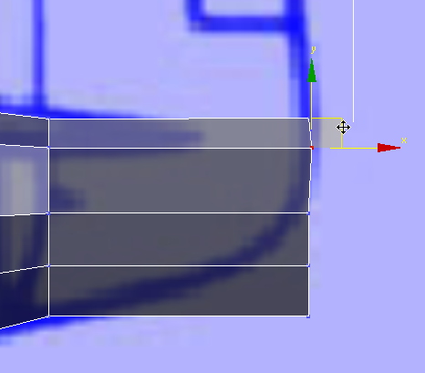
Finish extruding the fuselage:
 Extrude the fuselage once
more, this time to the very tip.
Extrude the fuselage once
more, this time to the very tip.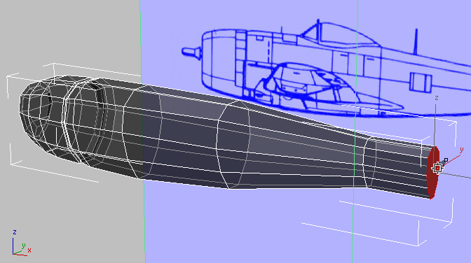
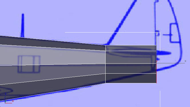
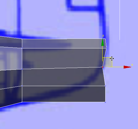
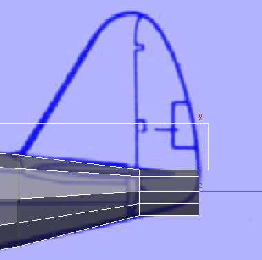
Front view
 scale the polygon down to match
the blueprint image.
scale the polygon down to match
the blueprint image.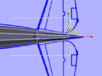
scale the polygon down to match
the size of the blueprint image.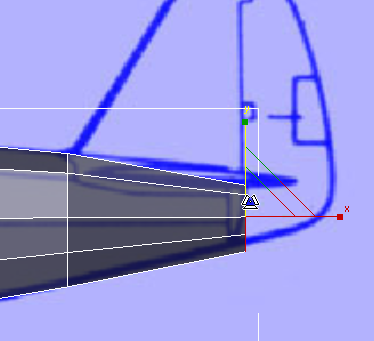
 move the polygon up to match
the contour of the fuselage.
move the polygon up to match
the contour of the fuselage.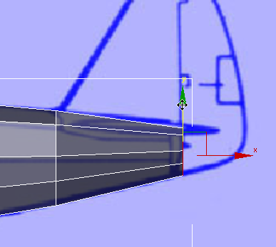
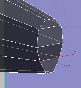
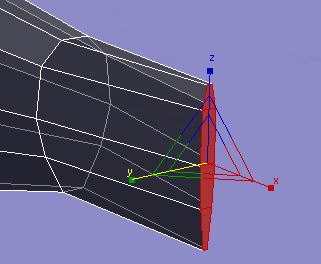
 (Orbit SubObject). Then orbit,
  pan, and
  zoom the Perspective viewport
to get a good view of the rear polygon.
zoom the Perspective viewport
to get a good view of the rear polygon.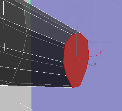
 Polygon Modeling panel, click
  (Vertex).
 click and Ctrl+click to select horizontal
pairs of vertices, then click ribbon Loops panel
click and Ctrl+click to select horizontal
pairs of vertices, then click ribbon Loops panel  (Connect) to add three horizontal
edges and subdivide the large polygon into four quadrangular polygons.
(Connect) to add three horizontal
edges and subdivide the large polygon into four quadrangular polygons.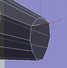
Polygon Modeling panel, click  (Polygon).
If all four rear faces
aren’t selected when you switch to the Polygon sub-object level,
then click and Ctrl+click to select them.
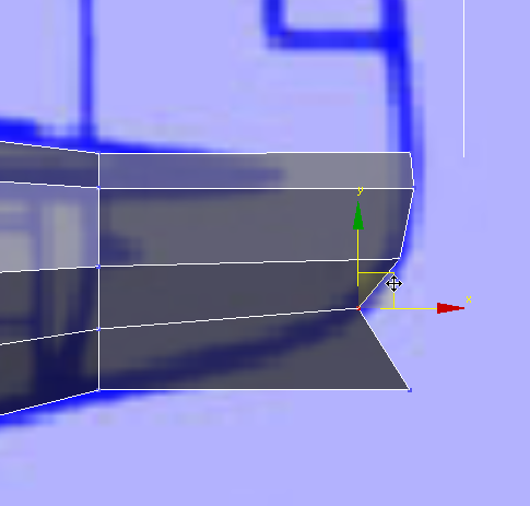
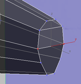
Extrude the faces to the
end of the tail.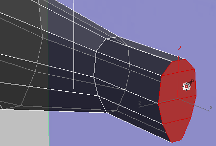
Front view
scale the faces down to
narrow the bottom-rear portion of the tail.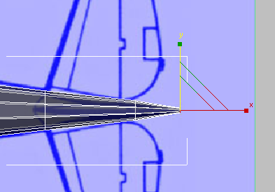
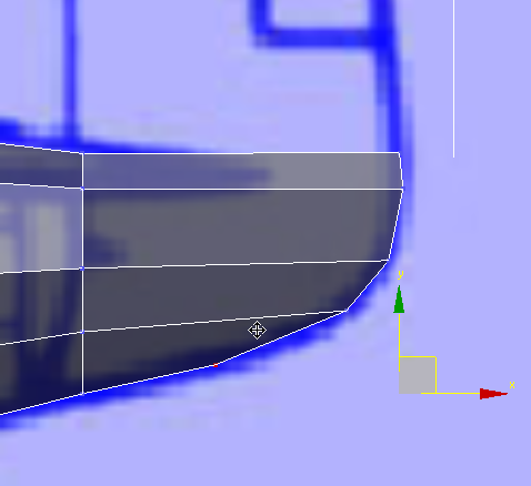
Perspective view
Polygon Modeling panel, click (Vertex).
move the vertex pairs to follow
the contour along the lower part of the tail.