Set Up Smoothing for the
Fuselage
NURMS smoothing does its job a little too well. There should be clear joins between some parts of the airplane; for example, between the wings and the fuselage. You can fix this by using smoothing groups. Smoothing groups change the appearance of the model without changing its geometry. Unlike NURMS, smoothing groups don’t increase the face count: This can be an important consideration if you are preparing your model for use in a game.
 (Zoom Extents All Selected).
 region zoom to get a good
view of the air intake.
region zoom to get a good
view of the air intake.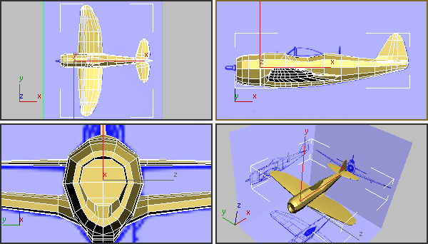
 (Polygon) sub-object level.
 Properties panel drop-down portion, click
  (SmGroups).
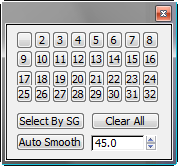
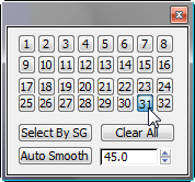
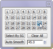
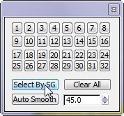
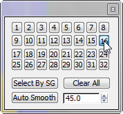
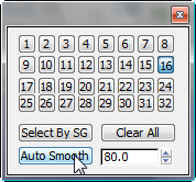
3ds Max opens the Smoothing Groups dialog.
![]()
This removes any default smoothing-group values that the faces might have.
Leave the Smoothing Groups dialog open: You will be using it throughout this lesson.
 Crossing state, then in
the Front viewport,
Crossing state, then in
the Front viewport,  drag a region to select
the faces at the very front of the engine cowl.
drag a region to select
the faces at the very front of the engine cowl.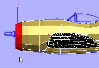
Modify Selection panel, click  (Grow) a couple of times,
until all of the engine cowl is selected.
(Grow) a couple of times,
until all of the engine cowl is selected.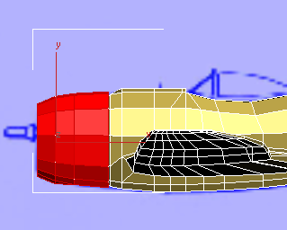
3ds Max smooths the faces of the engine cowl.
The basic idea of the smoothing-group values is simple: If two faces share the same value, 3ds Max smooths between them. If they have distinct values, there is no smoothing. (A face can have more than one smoothing-group value, which complicates matters, but we won’t use that feature in this tutorial.)
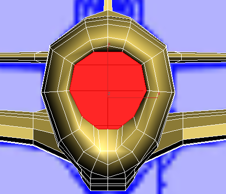
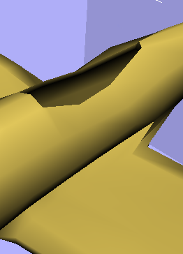
Remove smoothing from the air intake:
In this procedure, you don’t really remove smoothing from these faces: You just assign them to a different group from the rest of the cowl.
click and Ctrl+click to select the faces of
the air intake.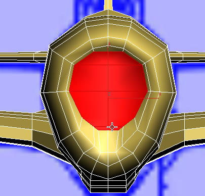
Now the air-intake faces look flat.
drag and Ctrl+drag to select the tips of
the wings.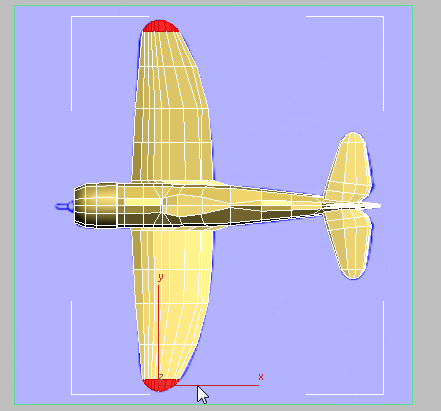
Modify Selection panel, click (Grow) several times, until
all of the wings are selected.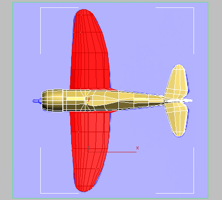
Perspective view
Smooth the horizontal stabilizers:
The steps for the horizontal stabilizers are almost the same as those for the wings.
drag and Ctrl+drag to select the tips of
the stabilizers.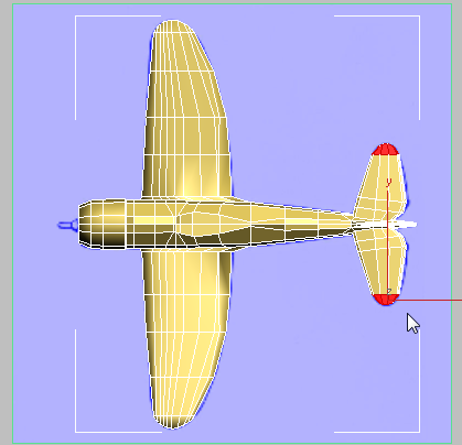
Modify Selection panel, click (Grow) a few times, until
all of the stabilizers are selected.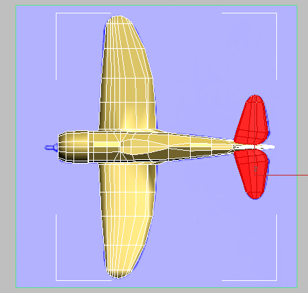
Smooth the remainder of the fuselage:
Now all of the model is smoothed correctly, except for the main fuselage. You can use the smoothing groups you’ve already created to help select it.
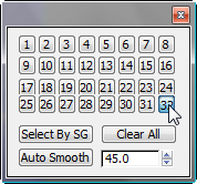
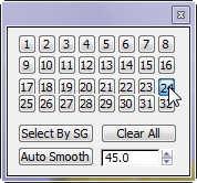
3ds Max opens a Select By Smooth Groups dialog. The buttons show only those smoothing groups that you’ve assigned so far.
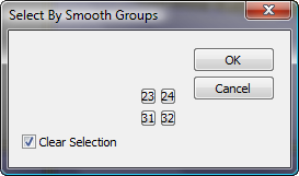
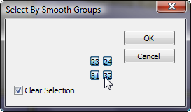
3ds Max selects those faces that already have a smoothing-group value assigned.
Now only the fuselage and tail are selected.
Smoothing the fuselage has an unexpeted effect: The faces around the cockpit are indented too deeply. You can use the Smoothing Groups dialog to fix this.
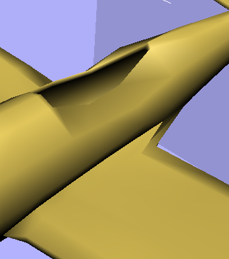
Unwanted indentation around the cockpit
(This is easier to see when the polygons are not selected, but you don’t need to deselect the polygons in your scene.)
3ds Max corrects the indentation around the cockpit.
Increasing the threshold value increases the chance of two faces to be smoothed together.
Use smoothing groups with NURMS smoothing:
 (Polygon) sub-object level.
Edit panel, turn on
(Polygon) sub-object level.
Edit panel, turn on  (NURMS).
Use NURMS panel, increase the number of
iterations to 2.
(NURMS).
Use NURMS panel, increase the number of
iterations to 2.
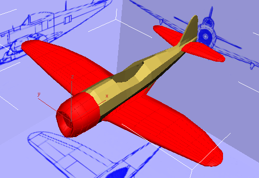
The default NURMS smoothing ignores the smoothing groups, and blends all faces of the P-47 together.
Use NURMS panel drop-down portion, open the Separate By
drop-down list, and turn on Smoothing Groups.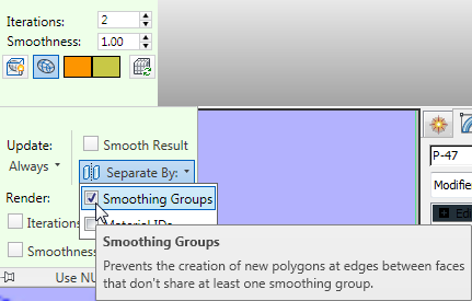
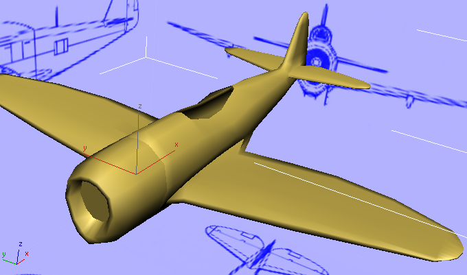
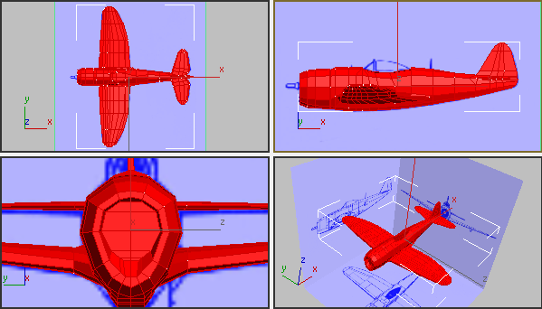
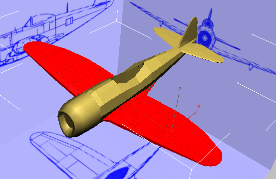
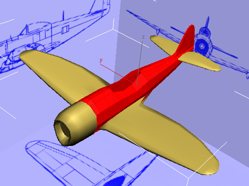
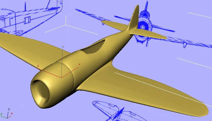
With smoothing groups taken into account, NURMS correctly shows seams between the air intake and the rest of the engine cowl, and between the wings and stabilizers and the main fuselage.
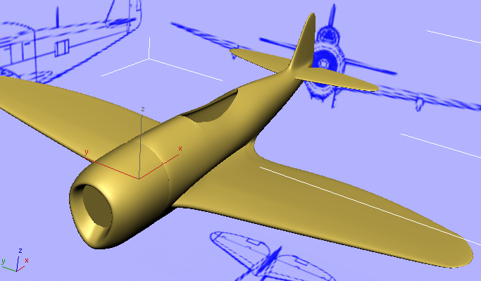
 (NURMS).
Although the smoothing provided by smoothing groups alone is not as good as NURMS smoothing, it could work for a low-polygon environment such as a game engine, or for viewing the model in a medium or long shot.