Add Detail to the Cockpit
Canopy
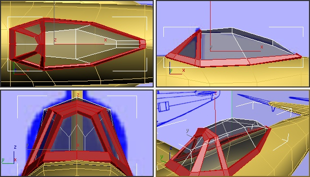
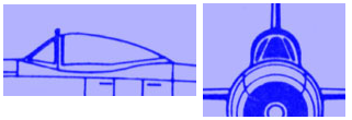
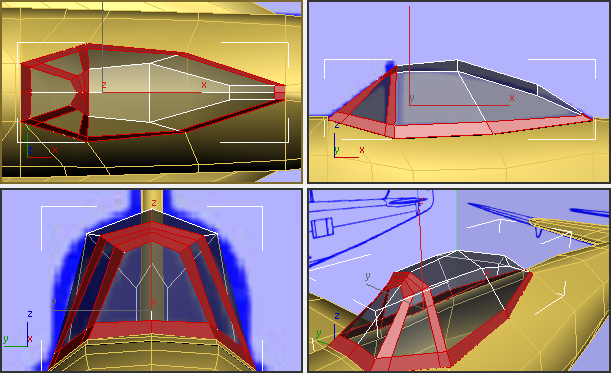
The cockpit canopy in this particular model is a bubble canopy, one of the canopy options for the P-47. The pilot sits in a glass bubble. The forward windshield is flanked by two side windshields, and the three windshields are backed by a metal strut like a rollbar.
 open \modeling\p47\p47_04.max,
 select the P-47.
On the ribbon
select the P-47.
On the ribbon  Polygon
Modeling panel, click Modify Mode.
Edit panel, turn off
Polygon
Modeling panel, click Modify Mode.
Edit panel, turn off  (NURMS).
Adjust the shape of the front windshield:
Now you can see the canopy again.
 Orbit,
  pan, and
  zoom the Perspective viewport
to get a closer view of the canopy.
zoom the Perspective viewport
to get a closer view of the canopy.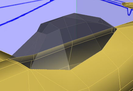
Select the canopy and if
you need to, press F4 to
display Edged Faces.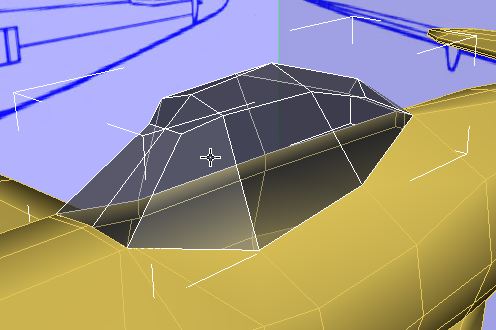
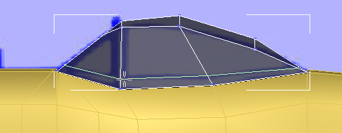
 (Vertex) sub-object level. Select the vertex at the
top center of the front windshield.
(Vertex) sub-object level. Select the vertex at the
top center of the front windshield.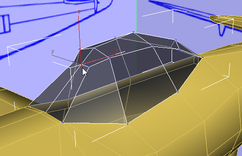
Edit panel, activate  (Constrain To Edge). Then
  move the vertex upward to
give the front windshield more of a peak.
move the vertex upward to
give the front windshield more of a peak.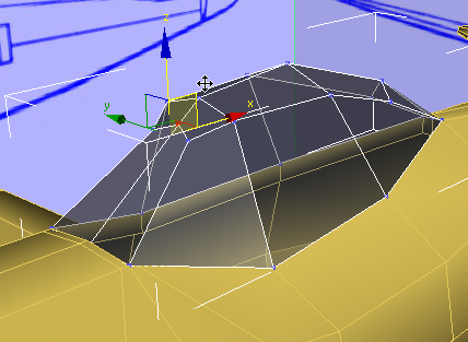
 (Select Object) to deactivate Move.
Edit panel, activate
(Select Object) to deactivate Move.
Edit panel, activate  (Constrain To None).
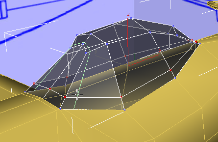
Add edges to reinforce the metal parts:
Edit panel, turn on  (SwiftLoop).
 (Edge) sub-object level.
Click and Ctrl+click to select the two edges
at the top front of the “rollbar” strut.
(Edge) sub-object level.
Click and Ctrl+click to select the two edges
at the top front of the “rollbar” strut.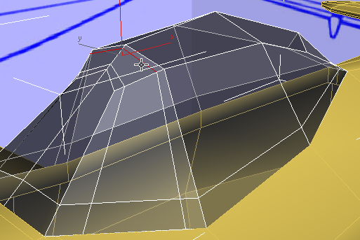
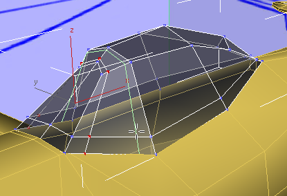
Edit panel, activate (Constrain To Edge). Then move the edges forward a
bit to give the strut a more even width.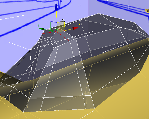
moving them back slightly
so the width of the frame is more even.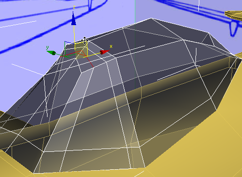
(Select Object) to deactivate Move.
Edit panel, activate (Constrain To None).
 (Polygon) sub-object level.
 (Zoom Extents All Selected).
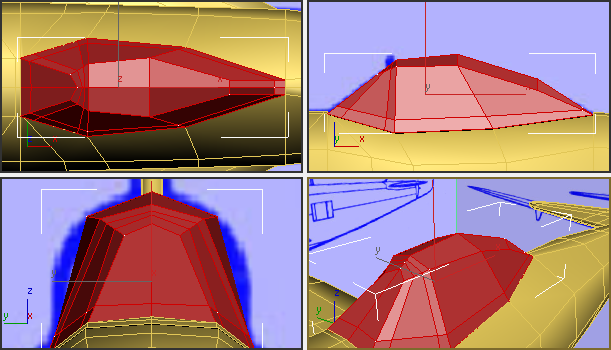
Click away from the canopy
to deselect all polygons. Then click and Ctrl+click
the polygons that correspond to the glass parts of the canopy. You
will need to use the Top viewport to select polygons that aren’t
visible in the Perspective view.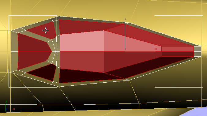
Top view
Perspective view
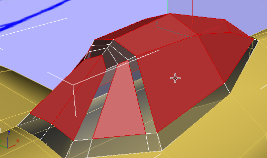
Polygons panel, Shift+click  (Extrude).
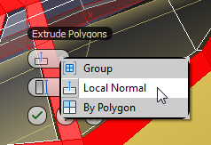
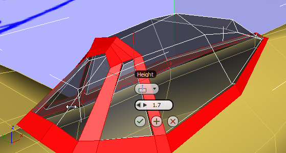
 (OK) to accept the extrusion.
Modify Selection panel, click
(OK) to accept the extrusion.
Modify Selection panel, click  (Grow).
This selects the side faces that were created when you extruded the metal parts. These faces should be metal, too.