The cockpit interior doesn’t require extensive detail, but adding it restores the fuselage model to being a single continuous surface.
Begin modeling the interior of the cockpit:
 zoom and
  pan to get a better view
of the top of the cockpit.
pan to get a better view
of the top of the cockpit.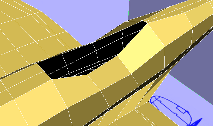
The P-47 fuselage now has a cockpit-shaped hole in it. To make the model a continuous surface again, you will add faces to form the interior of the hole.
 Polygon Modeling panel, click
  (Border).
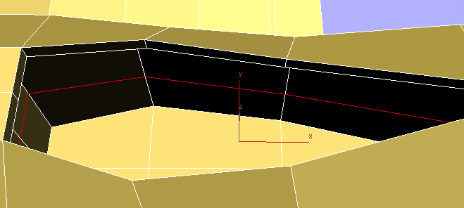
 Click the edge of the cockpit
to select all of the border edges.
Click the edge of the cockpit
to select all of the border edges.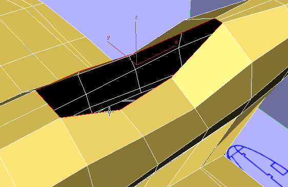
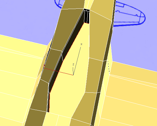
 Shift+move
the border downward to clone it and create a rim for the cockpit.
Shift+move
the border downward to clone it and create a rim for the cockpit.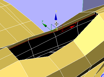
 Shift+scale
the new border uniformly, to make the cockpit interior wider than
its rim.
Shift+scale
the new border uniformly, to make the cockpit interior wider than
its rim.
Watch all four viewports when you do this step: You don’t want the sides of the cockpit interior to extend beyond the outside of the fuselage!
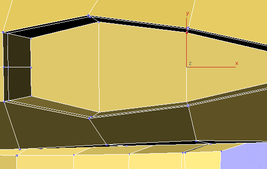
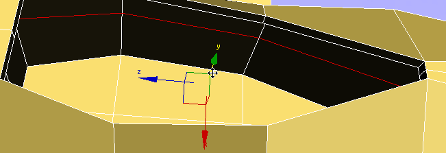
Shift+move
the cockpit border down, until the new border is just above the
level of the wings.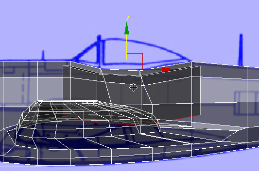
Align panel, click  (Align Y) to make the new
border horizontal.
(Align Y) to make the new
border horizontal.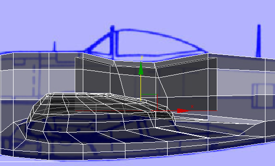
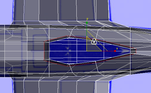
zoom and pan so you can see most
of the opening at the bottom of the cockpit.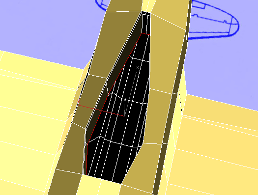
Geometry (All) panel, click  (Cap Poly).
3ds Max creates a polygon to cap the open border.
Zoom, pan, and  orbit the Perspective viewport
so you can see all of the floor of the cockpit.
orbit the Perspective viewport
so you can see all of the floor of the cockpit.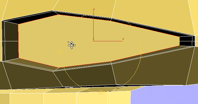
The polygon you just created is large and multisided, so you need to subdivide it into quadrangular polygons.
Polygon Modeling panel, click  (Vertex).
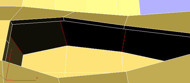
click and Ctrl+click to select the two vertices
where the forward edge loop stops at the cockpit floor, then on
the ribbon Loops
rollout, click
(Vertex).
click and Ctrl+click to select the two vertices
where the forward edge loop stops at the cockpit floor, then on
the ribbon Loops
rollout, click  (Connect).
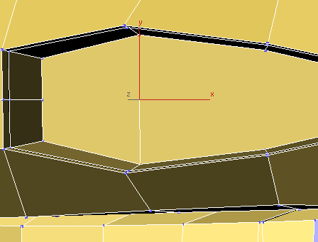
Polygon Modeling panel, click  (Edge).
Click an empty part of the
viewport to deselect any edges that are automatically selected,
then click and Ctrl+click to
select the two edges you just created.
(Edge).
Click an empty part of the
viewport to deselect any edges that are automatically selected,
then click and Ctrl+click to
select the two edges you just created.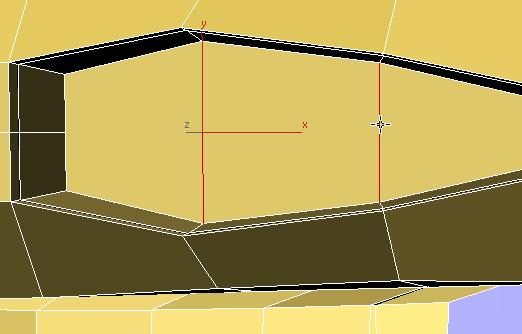
Loops rollout, click (Connect).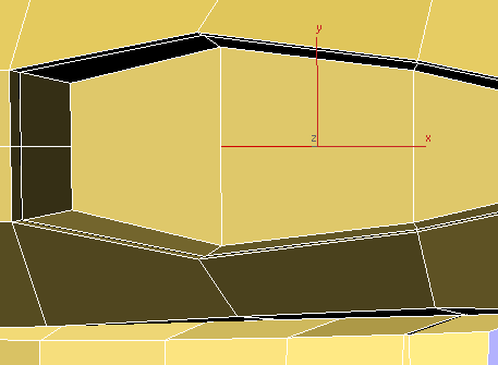
Edit
panel  (Cut) tool to connect the
vertex at the front floor level of the cockpit to the one at the
middle of the leading floor-level loop. Use the Cut tool again to
connect the vertex at the middle of the trailing flor-level loop
to the one in the middle of the back floor level of the cockpit.
(Cut) tool to connect the
vertex at the front floor level of the cockpit to the one at the
middle of the leading floor-level loop. Use the Cut tool again to
connect the vertex at the middle of the trailing flor-level loop
to the one in the middle of the back floor level of the cockpit.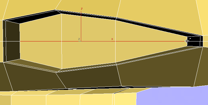
Now the polygons that form the interior of the cockpit are all quadrangular, and follow the overall pattern of the polygons that form the exterior of the fuselage.
Zoom, pan, and orbit the Perspective viewport
so you have a more edge-on view of the cockpit.
Click to select one of the
vertical edges along the side of the cockpit interior.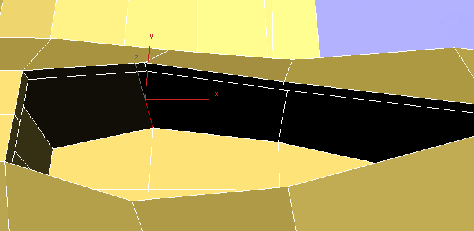
Modify Selection panel, click  (Ring).
3ds Max selects all the vertical edges, in a ring around the inside of the cockpit.
Loops panel, click (Connect).
3ds Max connects the edges with a new horizontal loop of edges.
Edit panel, activate  (Constrain To Edge).
Move the new edge loop up
a bit.
(Constrain To Edge).
Move the new edge loop up
a bit.
Edit panel, activate  (Constrain To None).
Zoom and orbit the Perspective viewport so
you can see the polygons at the front of the cockpit interior.
(Constrain To None).
Zoom and orbit the Perspective viewport so
you can see the polygons at the front of the cockpit interior.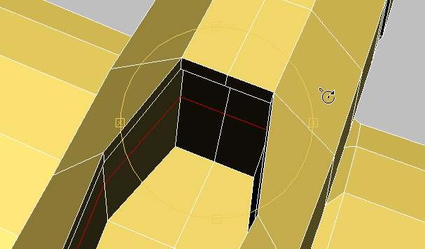
 (Polygon) sub-object level.
Click and Ctrl+click to select the two polygons
at the bottom of the front wall of the cockpit interior.
(Polygon) sub-object level.
Click and Ctrl+click to select the two polygons
at the bottom of the front wall of the cockpit interior.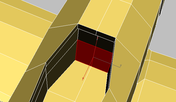
Polygons panel, turn on  (Extrude). Drag to extrude
the polygons forward, providing leg room for a pilot. (The two polygons
above the leg room but below the cockpit rim would be the location
of the instrument panel.)
(Extrude). Drag to extrude
the polygons forward, providing leg room for a pilot. (The two polygons
above the leg room but below the cockpit rim would be the location
of the instrument panel.)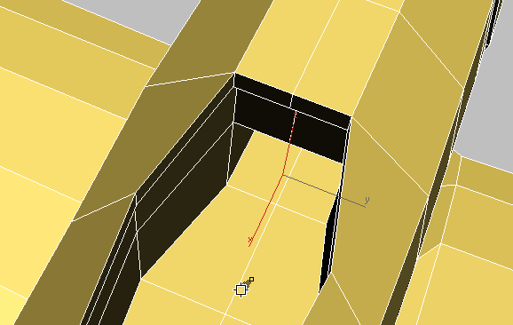
 (Polygon) sub-object level.


