


Block Out the Shape of
the Canopy
Now you give the cockpit canopy its overall shape. You will add more detail to the geometry in a later lesson.
Block out the shape of the canopy:
 Polygon Modeling panel, click
  (Vertex).
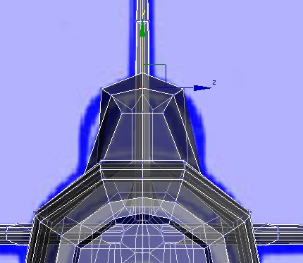
 move them to follow the
shape of the canopy in the blueprint image.
move them to follow the
shape of the canopy in the blueprint image.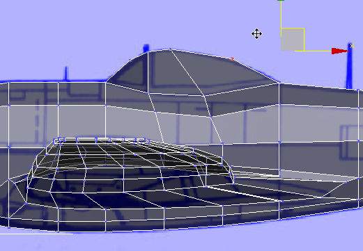
 scale the vertices along
the Y axis. This time, use the Left viewport to monitor your work
and match the model to the blueprint image.
scale the vertices along
the Y axis. This time, use the Left viewport to monitor your work
and match the model to the blueprint image.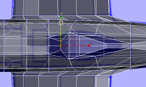
Left view
Left view
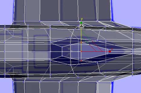
For this step, approximate the outer edge of the canopy, shown in dark blue.
Left view
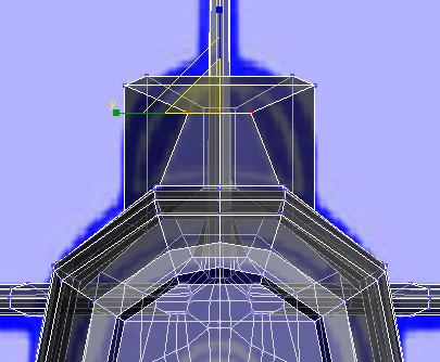
 click and Ctrl+click to select the three vertices
along the “ridgeline” of the canopy.
click and Ctrl+click to select the three vertices
along the “ridgeline” of the canopy.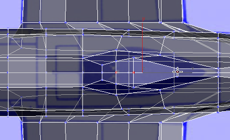
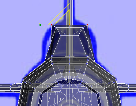
move these vertices up along the
Y axis while watching the outcome in the Left viewport.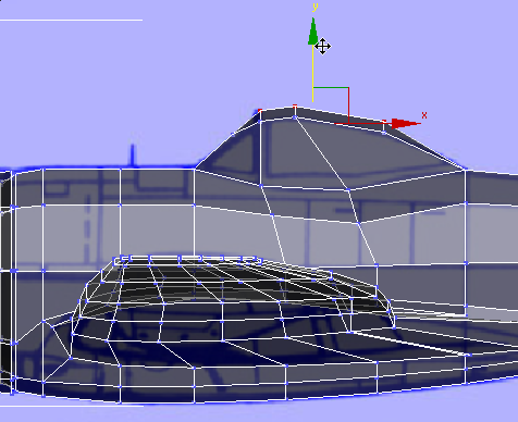
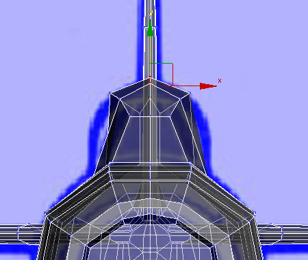
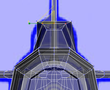
click to select only the
most forward of the three vertices you just moved.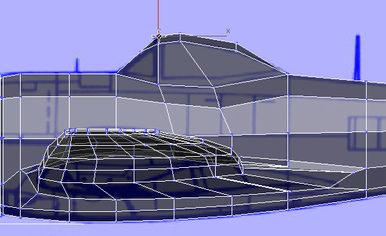
Move the vertex down a bit
in the Y axis to make the outline of the canopy look smoother.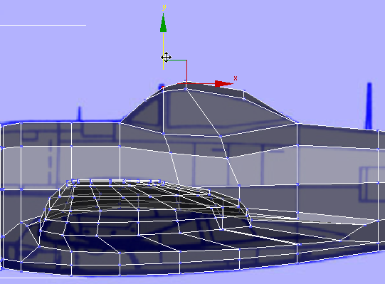
Left view
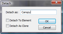
Detach the canopy and hide it:
The canopy will become a separate object from the fuselage. In this procedure, first you detach the canopy from the fuselage, and then hide it: The next lesson will concentrate on modeling the interior of the cockpit.
You finish adding detail to the canopy object in a lesson that follows.
Polygon Modeling panel, click  (Polygon).
 Crossing state; on the
  Modify panel Selection rollout, make
sure that Ignore Backfacing is turned off; then in the Front viewport, drag a selection box to
select all the polygons in the canopy.
Modify panel Selection rollout, make
sure that Ignore Backfacing is turned off; then in the Front viewport, drag a selection box to
select all the polygons in the canopy.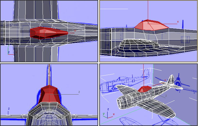
Geometry (All) rollout, click  (Detach).
Polygon Modeling panel, click  (Polygon) again to exit
the Polygon sub-object level.
Click to select the new Canopy object.
(Polygon) again to exit
the Polygon sub-object level.
Click to select the new Canopy object.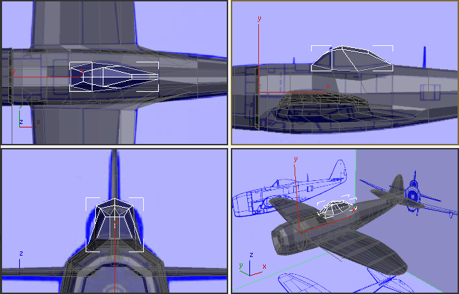
You will unhide the cockpit, and finish it, after you finish modeling the fuselage.