


Add Detail to Some Outbuildings
Next, you will add materials to the barracks. Materials for the barracks use texture maps, as the ammunition canister does, but they also use bump mapping to create a more three-dimensional appearance.
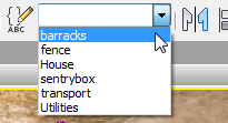
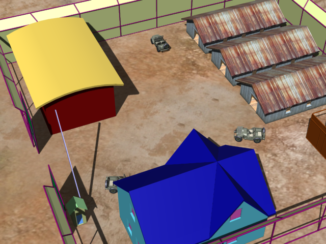
3ds Max displays the barracks in the center of the viewport, and hides the other scene geometry.
 (Orbit) and
  (Field-Of-View) to adjust the
view so you can clearly see the barrack walls.
(Field-Of-View) to adjust the
view so you can clearly see the barrack walls.
 (Select Object), then click
an empty area of the viewport to deselect the barracks set.
(Select Object), then click
an empty area of the viewport to deselect the barracks set.
 display the Material Editor.
 Propagate
Materials To Instances to turn it on. (When this option is turned
on, a check mark appears before its name.)
Propagate
Materials To Instances to turn it on. (When this option is turned
on, a check mark appears before its name.)
Like the oil tanks and generators, the barracks objects, roof, walls, and floors, are instances of each other. By turning on this option, you can apply a material to all the objects of one type by dragging and dropping to only one object.
Material/Map Browser
panel, at the left, locate Maps Standard Bitmap, and drag this map type into the
active View.
 (Show Map In Viewport) to
turn it on.
(Show Map In Viewport) to
turn it on.
The BarracksWalls material now has an image of the planking.
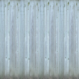
Planks texture for barracks walls
All three barracks now show the BarracksWalls material.
The planks texture shows dirt at the bottom of the wall, but with default mapping coordinates, the dirt appears just above each doorway, instead.
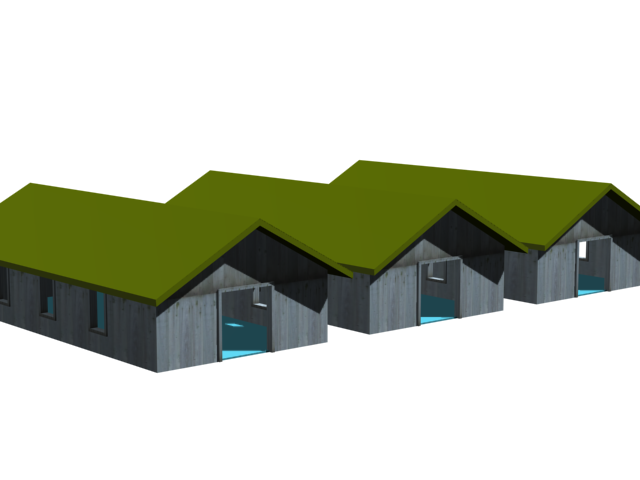
Planks texture appears on the walls, but is not aligned correctly.
Use UVW Map to adjust the planks:
 Select Barracks01-Walls, and
then go to the
Select Barracks01-Walls, and
then go to the  Modify panel.
Mapping group, change
the projection type to Box. Also set Length = Width = Height = 4.0m.
Modify panel.
Mapping group, change
the projection type to Box. Also set Length = Width = Height = 4.0m.
Now the planking texture is correctly aligned with the walls.

After applying UVW Map, the planks on the walls are aligned correctly.
Add a bump map to the planks material to improve realism:
If you take a closer look at the barracks, you can see that the texture looks good, but it also has a flat appearance, smoother than aged wood typically appears.
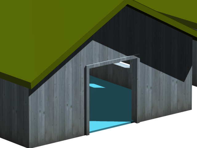
Barrack walls with a texture alone, and no bump mapping
You can improve the appearance of the plank walls by using bump mapping. Bump mapping makes an object appear to have a bumpy or irregular surface.
Material/Map Browser
panel, at the left, locate Maps Standard Bitmap, and drag another Bitmap node into
the active View.
3ds Max adds the node to the active View.
This map is simply a black-and-white version of the planks.bmp map itself.
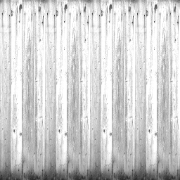
Black-and-white planks texture for bump mapping
Bump mapping uses intensities in the map to affect the surface of the material when you render it: white areas appear higher, and black areas appear lower. This is why the bitmap you use for bump mapping is often a black-and-white version of the map you use for texture.
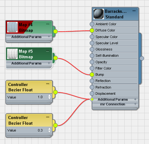
As it did for the other Bitmap nodes, 3ds Max adds a Controller node for the bump map’s Value.
 (Render Production) to see
the effect of the new map.
(Render Production) to see
the effect of the new map.
The barrack walls with bump mapping
To get an even more weathered look, you can increase the bump mapping Amount.
(Render Production) again.
Now the planks appear extremely weathered.

The barrack walls with increased bump mapping
You will use a similar method for the roofs and floors of the barracks.
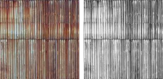
Left: Texture map for the barrack roofs
Right: Bump map for the barrack roofs
Field-Of-View so you have
a good view of the barrack roofs.
Select Barracks01-Roof.
active View.
Material/Map Browser
panel, at the left, locate Maps Standard Bitmap, and drag this map type into the
active View.
 (Assign Material To Selection),
and then click (Show Map In Viewport) to
turn it on.
(Assign Material To Selection),
and then click (Show Map In Viewport) to
turn it on.
In the viewport, the map appears on the barrack roofs. However, it is oriented the wrong way: the corrugated plates should lie along the slope of each roof instead of lengthwise.
Modify panel, and use the
Modifier List to apply a UVW Map modifier.
At first this appears to lose the W-Angle correction you just made, but changing the modifier alignment will fix that.
Alignment group, choose
Y as the alignment axis.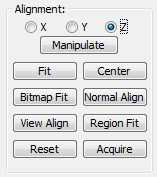
Mapping group, change
Length to also equal 7.04m.
(Make sure you leave the UVW Map projection set to Planar, the default.)
Material/Map Browser
panel, at the left, locate Maps Standard Bitmap, and drag another Bitmap node into
the active View.
(Render Production) to see
the effect.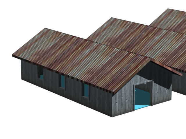
The barrack roofs with bump mapping
At the eaves of the roofs, the texture “slops over” a bit. In this scene, it isn’t a problem because usually you will render the barracks from a distance. Of course, the bump mapping isn’t too apparent at a distance, either. Whenever you texture a scene, bear in mind how much detail you want to use to make the scene believable.
Texturing the barrack floors should now be a familiar process
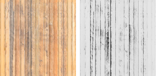
Left: Texture map for the barrack floors
Right: Bump map for the barrack floors
Select Barracks01-Floor.
(Assign Material To Selection),
and then turn on (Show Map In Viewport).
Apply a UVW Map modifier
to Barracks01-Floor. Leave the projection
set to Planar. Set Length = Width = 4.0m.
You don’t need to adjust the orientation of the floorboards.
Now the barracks are completely textured.
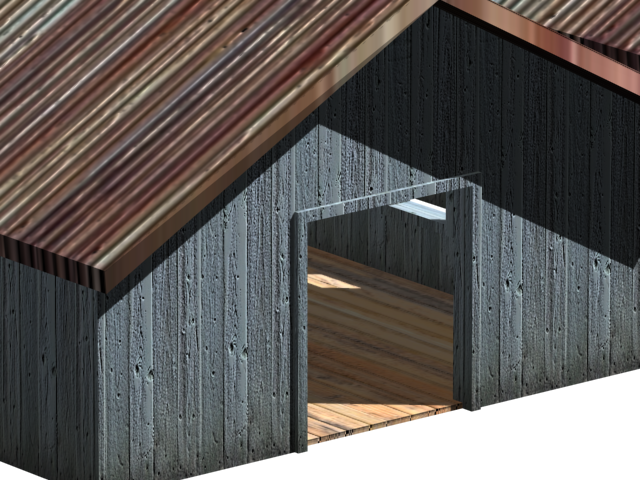
Close-up of one barrack with textures for roof, walls, and floor
Use the Barrack Materials for the Sentry Box
Now that you have textured the barracks, you can use the same materials for the sentry box. The trick is to use the same materials and the same UVW Map settings.
Camera02.
This gives you a view of the completed barracks, and the unfinished sentry box.
The new view lets you see the roofs, walls, and floors of the completed barracks, and also the roof, walls, and floor of the sentry box, which doesn’t yet have materials applied.
Camera02 view with finished barracks to the right, unfinished sentry box to the left.
Changing to a perspective view doesn’t change what appears in the viewport, but in the perspective view, you can navigate without changing the camera settings.
Copy the barracks floor material:
Click one of the Barracks0X-Floor objects
to select it.
Ctrl+drag
the UVW Mapping entry in the floor object’s modifier stack, and
drop this modifier instance over the floor of the sentry box. (Before
it has a material, the floor appears blue.)
The sentry box floor now has the correct mapping, but it still needs its material.
Now the floor has both the material and the correct mapping.
Copy the roof and wall materials:
If the material is no longer visible in the active View of the Material Editor, then on the Browser panel open the Scene Materials group, drag the material into the active View, and choose Instance.
The sentry box with the same materials as the barracks
Create a new, 3D material for the sentry bar:
For the sentry bar, which blocks or permits vehicle access to the compound, you can use a simple material with a procedural map named Gradient Ramp.
(Orbit) and (Field-Of-View) to adjust the
view so the sentry bar is clearly visible.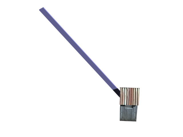
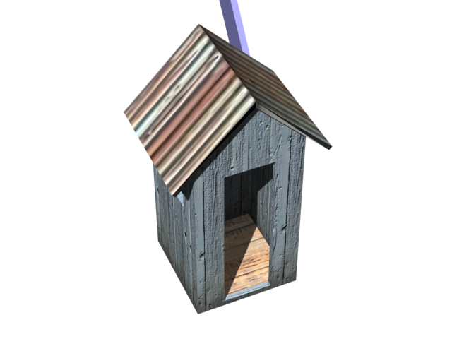
Isolated sentry box with a view of the bar
Select the sentry-bar object.
Maps Standard group, drag a Gradient Ramp node
into the active View. Wire this node to the Diffuse Color component
of the SentryBar material.
(Assign Material To Selection) and (Show Map In Viewport).
Gradient Ramp is a 3D procedural material like the Noise material you used for the generator casings.
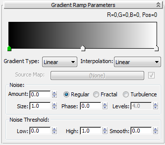
The gradient display changes to two solid colors, one of them black.
Gradient Ramp with solid colors
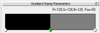
Double-click the middle slider (shown in green) to change the color to the right of the slider.
The material changes from two color areas to multiple stripes.
Now the stripes have an angle to them.
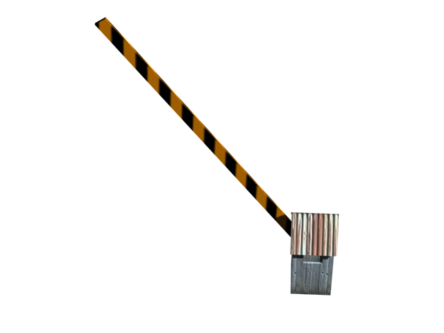
Isolated sentry box with the completed sentry bar
 open army_compound01.max.