You begin with a scene that has only a few materials in it.
 (Open File), navigate to \scenes\materials_and_mapping\intro_to_materials\ and
open army_compound.max.
Except for the vehicles, the jeeps and helicopter, this scene contains no materials. The buildings and terrain have a featureless, plastic look to them that is typical of newly created geometry in 3ds Max.
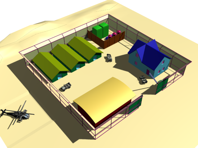
The field headquarters before you apply materials
You’ll begin by adding textures to the utility containers in the fenced area at the rear of the compound.
Isolate the utility containers:
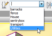
This command is in the upper-right, Display quadrant.
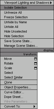
3ds Max displays the utility containers in the center of the viewport, and hides the other scene geometry.
 (Orbit) to adjust the view
so you can see all five containers clearly.
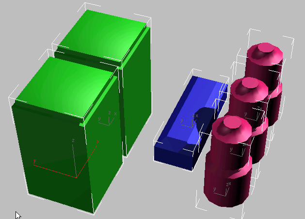
The isolated set of containers
Now you’re ready to begin creating materials for these objects.
Apply a basic material to the oil tanks:
 (Select Object).
 (Material Editor) to open the
Slate Material Editor.
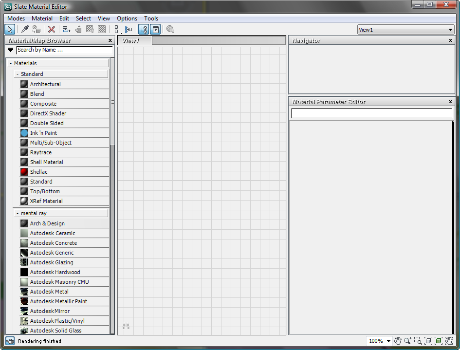
Also, to see changes in the viewport, it will help to minimize the Slate Material Editor while you work, and then restore it when you need to work on materials some more.
The Material Editor is a sort of workbench for creating, adjusting, managing, and applying materials to objects. The main portions of its interface are:
 Standard
  Standard, then drag
the Standard entry from the Browser and drop it in the active View (the
large panel labeled View1 in the center of the Editor).
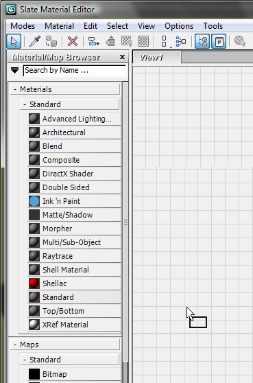
A node for the Standard material appears in the active View.
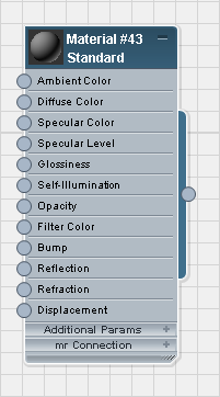
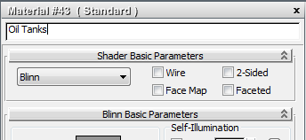
Notice that as you enter the name in the Name field, the name in the title bar of the node also updates.
It is good to get in the habit of naming a material as soon as you create it. In a complex scene, intelligible material names are useful.
3ds Max opens a Color Selector dialog.
Use the Red/Green/Blue controls on the Color Selector to choose a yellow color. Set Red = 200, Green = 200, and Blue = 0.
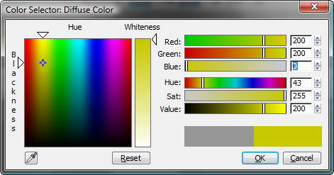
The diffuse color of a material is the color that appears under diffuse, or scattered, light. It is what we usually think of as “the” color of a material, and what you will set first, when you create a basic material such as this one.
 (Assign Material To Selection).
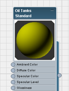
Angled corners on a material preview mean that the material has been applied to at least one object in the scene. When the angled corners are solid white, as they are in this case, the material is said to be hot. When you make changes to a hot material, the scene changes immediately, and usually the viewport display shows the material changes you have made.
You will take advantage of adjusting a “hot” material in the next set of steps.
Make sure that the three oil tanks are still selected, and that the Oil Tanks material is still active.
Bright highlights appear on both the sphere in the preview, and the oil tanks in the viewport.

Left: Preview with the oil tank material
Right: Specular highlight controls with Glossiness = 32
As you can see the preview and in the graph to the right of the Specular Highlight and Glossiness controls, the highlight is now narrower. Specular Level controls how bright highlights are, while Glossiness controls highlight width. In general, shinier materials have smaller highlights.
You have used basic material controls, Diffuse color, Specular Level, and Glossiness, to create a simple material that has the appearance of a moderately shiny paint. This completes the material for the oil tanks.
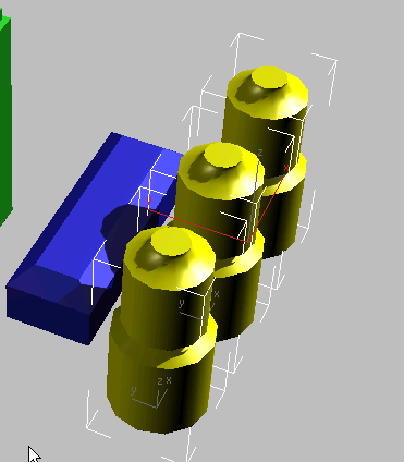
The oil tanks with their material
Apply a texture map to the ammunition canister:
For the ammunition canister, you will use a bitmap. Bitmaps are a versatile way to add visual detail to scenes, and we use them extensively in this scene. When a bitmap is used to provide an object’s color, it is also known as a texture map. The texture map you apply to the canister shows a section of metal plating with a “checkered” pattern.
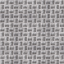
Texture map for the ammunition canister
 active View, move the Oil
Tanks node to one side.
 Material/Map Browser
panel, at the left, locate Maps
  Standard
  Bitmap, and drag this map type into the
active View.
3ds Max adds this Bitmap node to the active view.
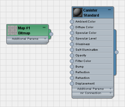
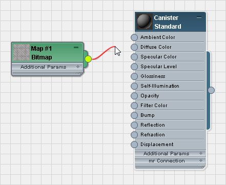
Drop the wire on the input socket for the Canister node’s Diffuse Color component.
The Bitmap is now wired to the material.
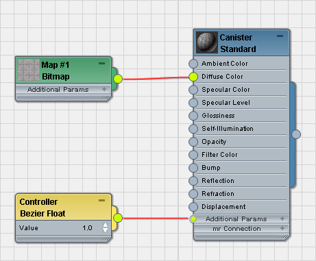
After you wire the Bitmap, 3ds Max also adds a Controller node (you could use this, if you wanted, to animate the Bitmap’s Amount value).
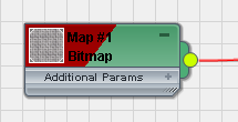
 (Show Map In Viewport) to
turn it on.
A red diagonal shape appears in the Bitmap title bar, to indicate that Show Map is active.
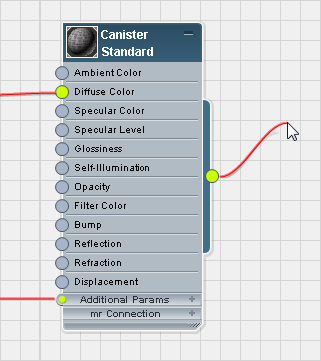
Dragging from the output socket of the Canister material
3ds Max applies the Canister material to the ammunition canister.
Dragging and dropping
from the output socket of a material node is an alternative to using  (Assign Material To Selection).
Adjust the metal plate mapping:
If you  zoom in, you can see that
the mapping is not as good as it could be. The top and sides of
the canister look all right, but there is streaking where the top
of the canister has beveled faces.
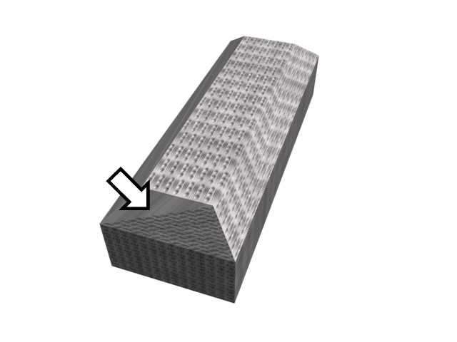
Streaks in the texture when using the default mapping
To fix this, you use a modifier called UVW Map.
 Select the canister object,
which is named Ammo, and go to the
  Modify panel.
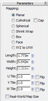
 Mapping group, choose
Box.
The radio buttons at the top of the Mapping group (Planar, Cylindrical, Spherical, and so on) tell the UVW Map modifier how to project the map onto the object. Box mapping projects the map from all six sides, so the texture display is more uniform.
Now the mapping is uniform and looks good from any angle.
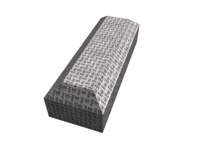
The texture corrected using UVW Map
Clean up the Slate Material Editor interface:
 active View, click a
node to select it, then press Ctrl+A to select
all nodes in the View.
Deleting nodes from the
active View simply cleans up the View for further work. It does
not remove the materials from the scene: You can still see the materials
you created (as well as in the Material/Map Browser  Scene Materials group.
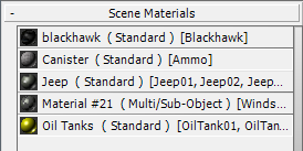
If you need to edit a material again, you can drag it from this group and into the View as an instance.
Apply a 3D material to the generators:
Finally, for the generators, you will use a 3D procedural map. A bitmap is simply a digital image such as a scan or a photograph. A 3D map, on the other hand, is generated by 3ds Max.
 Select Generator01 and Generator02, the
large boxy objects to the left.
 (Assign Material To Selection),
and then click
  (Show Map In Viewport) to
turn it on.
The map appears in the viewport, but the camouflage pattern isn’t very apparent.
Now the generator casings have a recognizable camouflage pattern. A bonus of the procedurally generated 3D Noise texture, is that the pattern is not quite the same on either generator. (This effect is more apparent when you render the scene: In viewports, both generators look much the same.)
You now have a reasonably realistic texture for all of the containers in the utilities area of the compound.
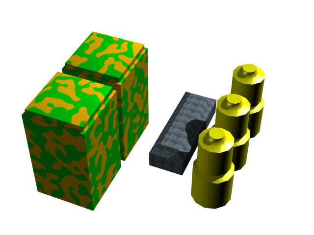
Utility containers with their textures
Apply a texture map to the terrain:
For the last step in this lesson, you will apply a texture to the terrain beneath and surrounding the compound.
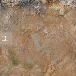
Terrain texture for the army compound
 Material/Map Browser
panel, at the left, locate Maps
  Standard
  Bitmap, and drag this map type into the
active View.
 (Show Map In Viewport) to
turn it on.
The Ground object turns brown, but it doesn’t show the texture map. This is a sign that the object doesn’t have mapping coordinates.
Primitive objects such as boxes and spheres have default mapping coordinates, but editable geometry such as Ground, which is an Editable Poly, does not. You have to assign mapping coordinates by applying UVW Map.
 Select the Ground object,
and go to the
  Modify panel.
For the terrain, the default Planar projection works fine, and the map terrain.jpg is already the right size for the scene, so your work in this lesson is now complete.
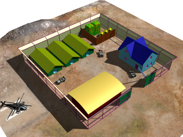
Army compound with textured utility containers and terrain