


Creating a Normal Bump
Map
First, you use the Render To Texture feature to create the normal bump map.
 (Open File) and from the \materials_and_mapping\normal_bump_map folder,
open pavers.max.
(Open File) and from the \materials_and_mapping\normal_bump_map folder,
open pavers.max.
The scene consists of a source object, a tile of spheres sculpted to resemble rocks set in mortar. Directly above is the target object, a simple two-dimensional plane.
 select the target plane object, Proj-Plane, and
go to the
select the target plane object, Proj-Plane, and
go to the  Modify panel.
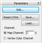
This modifier sets out the mapping coordinates of the plane object, so that the textures of the source object can accurately be projected onto it.
On the Parameters rollout  Channel group, notice
that the mapping coordinates are automatically stored on Map Channel
1.
Channel group, notice
that the mapping coordinates are automatically stored on Map Channel
1.
Here, you will use the Render To Texture tool to define various projection setup parameters.
Render To Texture.
General Settings rollout Output group, define
the output path where you want to save the diffuse, normal bump,
and height map textures you are about to create.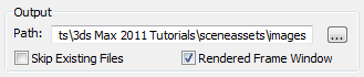
By default, the output is saved to the \3dsmax\sceneassets\images folder of your 3ds Max project, but you might want to specify a different storage location.
Projection Mapping group,
turn on Enabled. Since the plane object you will bake the texture
to consists of only a single flat surface, turn off Sub-Object Levels.
If you wanted to bake textures of objects onto multiple surfaces (for example, onto each face of a box), you would keep Sub-Object Levels turned on.
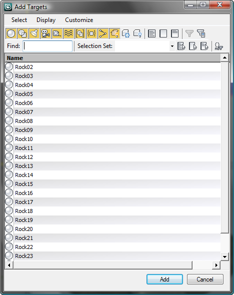
Here, you choose which objects you want to bake onto the plane object.
The drop-down list in the Projection Mapping group changes from (No Projection Modifier) to Projection, indicating that a new Projection modifier, containing the items you just selected for projection, has been placed on the stack for the plane object.

The height map defines the stone and mortar topography of the source object. To generate the map, you must determine both the farthest and closest points between the source and plane object.
 zoom in slightly until you
can see the mortar regions clearly.
zoom in slightly until you
can see the mortar regions clearly.
In the next two steps, be sure that you are directly above the plane. Height selection will work only if you are above the target object.
 eyedropper button to the
right of the Min Height field. Click through the plane, above the
mortar between the rocks. The value of Min Height changes to –100.
eyedropper button to the
right of the Min Height field. Click through the plane, above the
mortar between the rocks. The value of Min Height changes to –100.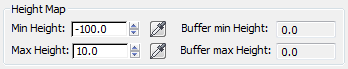
eyedropper button next to
the Max Height field and then click through the plane, over the
highest rock in the scene. This is Rock10, along
the upper-right edge of the plane in the Top viewport. Try to find
a value between –40.0 and –20.0.
 Close the Projection Options
dialog. In the Render To Texture dialog Objects To Bake rollout Mapping Coordinates group, choose Use Existing Channel,
if it is not already chosen.
Close the Projection Options
dialog. In the Render To Texture dialog Objects To Bake rollout Mapping Coordinates group, choose Use Existing Channel,
if it is not already chosen.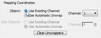
The Use Existing Channel option indicates that you want to use the texture-mapping coordinates you created from the UVW Modifier at the beginning of this lesson, rather than letting 3ds Max create new texture-mapping coordinates on the fly.
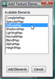
Define the texture to be baked:
Now that the projection method has been defined, the next step is to add the diffuse, normal bump, and height maps that, when combined, will form the texture to be baked onto the plane object.
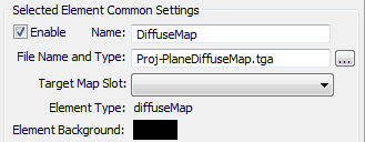
A new Diffuse entry appears
in the Output rollout Selected
Element Common Settings group. The file name of the diffuse map
to be created displays in the File Name and Type field.

A new Normals entry appears on the Output rollout, below the Diffuse map entry.

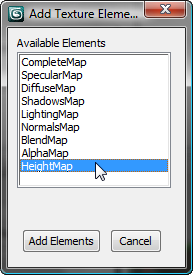
At this point, you have defined all the basic elements and settings for creating diffuse, normals bump, and height maps.
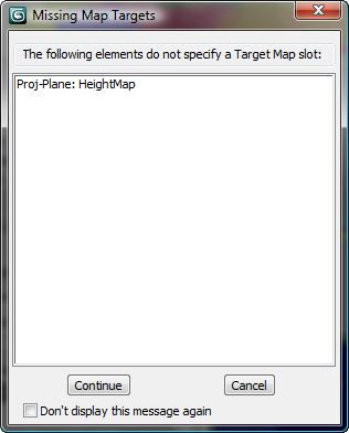
Click Continue to dismiss the Missing Map Targets message box. We deliberately left the height map unassigned, because in the next lesson, you will assign it separately.
If the Files Exists dialog displays, click Overwrite Files.
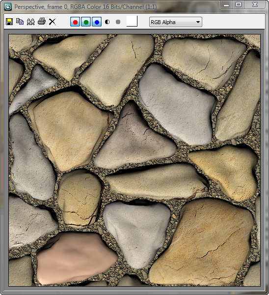
The rendering shows only the information from the diffuse map. The normal bump and height maps have also been baked into the texture of the plane, but they are not visible. In the next lesson, you will use the Material Editor to display the complete projected texture in the viewports.
Close the rendered frame
window.