


Visualizing the Projection
With DirectX shading, you can view the effect of normal bump mapping in viewports.
 open pavers_view.max.
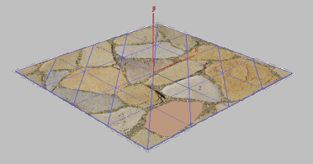
 Select the plane object.
Right-click it, and choose Isolate Selection from the quad menu.
Select the plane object.
Right-click it, and choose Isolate Selection from the quad menu.
Next, you will hide the plane’s selection cage, which was generated by the Projection modifier you added earlier.
 Modify panel, open the Modifier
List and apply a Poly Select modifier. This adds the modifier to
the top of the plane’s modifier stack and hides the selection cage.
Modify panel, open the Modifier
List and apply a Poly Select modifier. This adds the modifier to
the top of the plane’s modifier stack and hides the selection cage.
 Slate Material Editor.
 (Pick Material From Object),
and click the plane object to display its material in the active
View.
(Pick Material From Object),
and click the plane object to display its material in the active
View.
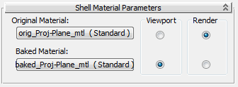
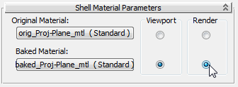
As the rollout shows, the Shell material contains two types of material: the originally assigned plane material, which displays only when rendered, and the baked material obtained from the source object, which displays only in viewports.
 (Zoom Extents) to see the
whole material tree.
(Zoom Extents) to see the
whole material tree.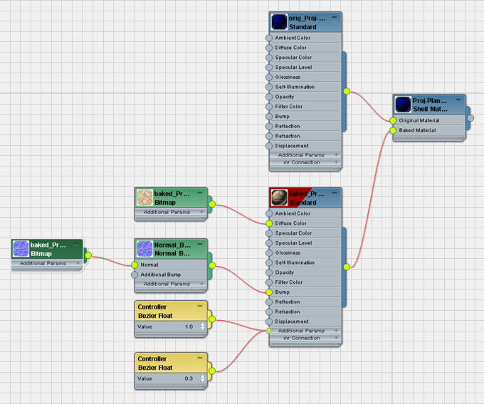
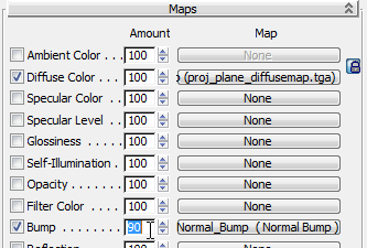
At the right is the top-level node, the Shell material you just inspected. Next to the left are the two sub-materials: The original, renderable material is above, and the baked, hardware material is below. The baked material has a Bitmap node and a Normal Bump map node (each of these has an associated Controller node). Finally, the Normal Bump node uses the NormalsMap bitmap you rendered in the previous lesson.
 Cropping/Placement group,
click View Image.
Cropping/Placement group,
click View Image.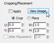
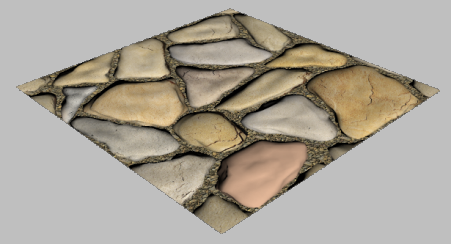
3ds Max displays the normal bump map you created earlier, which now is applied to the plane object.
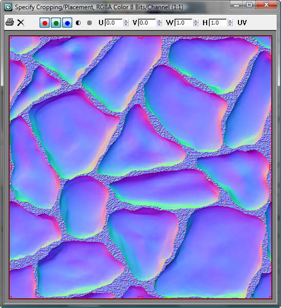
The colors in the map are significant. The reason normal bump maps convey so much more detail than ordinary bump maps is that normal bump maps use the entire RGB spectrum for surface detail information, whereas ordinary bump maps only use a single grayscale. The blue channel conveys vertical depth information, and the red and green channels enhance this information by providing a direction vector for the orientation of the surface normal at each point. This results in higher realism.
 Close the Rendered Frame
Window.
Close the Rendered Frame
Window.
Use hardware shading to display the map:
 zoom in to get a closer view
of the plane.
zoom in to get a closer view
of the plane.
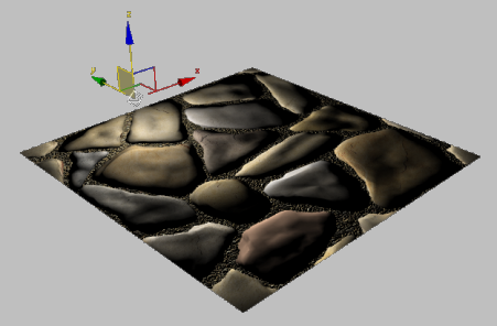
The flat surface of the plane object takes on a greater, three-dimensional degree of detail.
Next, you will add a standard Omni light to the scene to see how effectively the normal bump map, when combined with a standard Omni light, provides a sense of depth to the object.
 Create panel, turn on
  (Lights). Choose Standard
from the drop-down list, then click Omni to turn it on.
(Lights). Choose Standard
from the drop-down list, then click Omni to turn it on.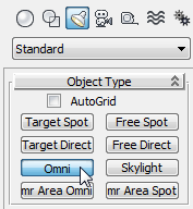
 Move the light across the
stones.
Move the light across the
stones.
You might need to move the light vertically as well, to position it above the plane.
Even though this object is a flat plane, notice how the light and shadow play across the stones as if the geometry was a raised surface.
Try rendering with both renderers:
 orbit so the plane is almost
horizontal, then press F9 to
render the plane.
orbit so the plane is almost
horizontal, then press F9 to
render the plane.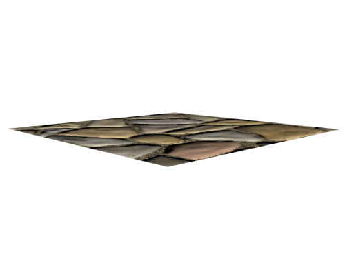
Notice how the edges of the plane still appear straight and two-dimensional.
The 3D relief you’ve achieved so far with the diffuse and normals bump maps is usually acceptable when you model for games development. For other uses, such as cinematics, you might need to take things one step farther.
To complete the effect, you will use the height map you created earlier and render it with the mental ray renderer.
 (Render Setup) to open the
Render Setup dialog. On the Common tab, scroll down to the Assign
Renderer rollout, then click
(Render Setup) to open the
Render Setup dialog. On the Common tab, scroll down to the Assign
Renderer rollout, then click  (Choose Renderer) for the
Production renderer.
(Choose Renderer) for the
Production renderer.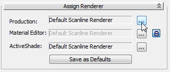
 Render the plane again.
 (Clone Rendered Frame Window),
then minimize the two frames.
(Clone Rendered Frame Window),
then minimize the two frames.
Now you will add the Height map to the rendering.
Select the plane object.
Extended Shaders group,
click the  lock button for Displacement
to unlock Displacement and enable its controls.
lock button for Displacement
to unlock Displacement and enable its controls.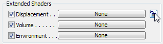
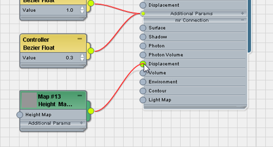
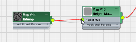
mental ray Height Map Displacement, and drag this map
type to the Active View.
 zoom so you have a good
view of both the baked_Proj-Plane_mtl / Standard material
node and the new Height Map Displacement node.
zoom so you have a good
view of both the baked_Proj-Plane_mtl / Standard material
node and the new Height Map Displacement node.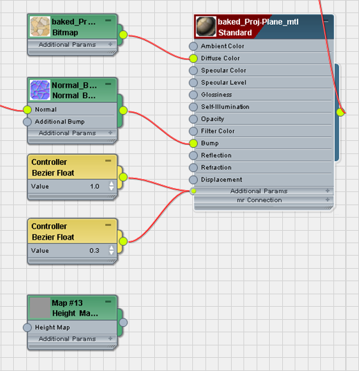
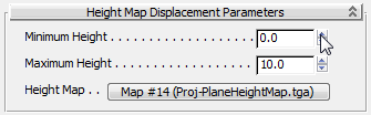
Standard Bitmap, and drag this
map type to the active View.
On the file dialog, choose proj-planeheightmap.tga.
Like the Diffuse and
Normal Bump maps, this file should be located in \sceneassets\images, or in the
folder you specified earlier on the Render To Texture General Settings rollout.
Render the Perspective viewport.
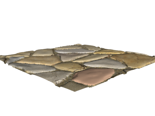
The geometry has been pushed up based on the displacement map generated by the mental ray engine and added to the rendering.