With the introduction of the spline as a guide, now the brick material can properly follow the contours of the arch object. However, in the present state of mapping, the bricks are too large and they are mapped vertically up the arch columns instead of horizontally across them. In this lesson, you use the Edit UVWs dialog to adjust the mapping visually so that the bricks map properly.
Set up the Edit UVWs dialog, and inspect the brick map:
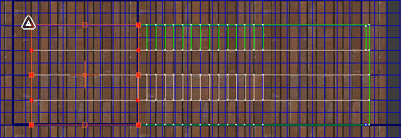
3ds Max opens the Edit UVWs dialog.
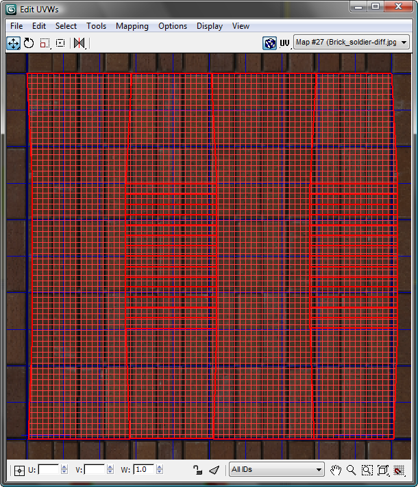
Arch object displayed as grid of UVW faces and vertices
The window in the Edit UVWs dialog shows a flattened representation of the arch object. There are four red vertical panels made up of UVW faces and vertices. The panels represent the inner, outer, left, and right face of the arch.
 zoom tool to zoom out slightly.
The surface of the arch object is currently mapped to a single tile of the brick-soldier material.
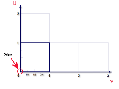
The square occupied by the flattened arch object corresponds to the dark square in the next diagram, which shows the coordinate system of the Edit UVWs window.
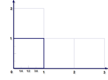
The texture you apply to the arch object will be mapped to this area, whose coordinate system ranges from 0, 0 to 1, 1.
 View Image File, and
on the View File dialog, navigate to the folder \sceneassets\images\, click to
highlight brick_soldier-diff.jpg and
click Open.
View Image File, and
on the View File dialog, navigate to the folder \sceneassets\images\, click to
highlight brick_soldier-diff.jpg and
click Open.
3ds Max opens an image file viewer, showing that brick-soldier-diff.jpg is a square image. At present, it is mapped on a one-to-one basis using UVW coordinates that range from 0 to 1. Outside of the square bounded by the 0 to 1 values, the same image is tiled two more times in each direction.
 Close the image file viewer.
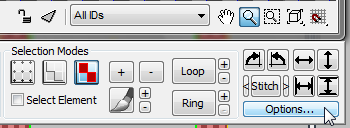
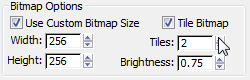
3ds Max opens a further Bitmap Options group that appears below the Soft Selection group.
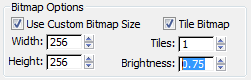
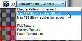
The bitmap in the Edit UVWs window becomes brighter and easier to see.
 (Vertex Sub-Object Mode).
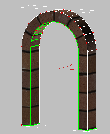
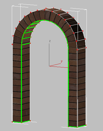
By switching to the Vertex sub-object mode, you can see how the Unwrap UVW modifier has slightly warped the contours of the arch object. You need to straighten out these contours.
Warped contours of the unwrapped arch object
 (Move), and region-select
all the vertices of the left outside edge.
(Move), and region-select
all the vertices of the left outside edge.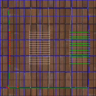
UVW vertices of left outside edge selected
For these vertices to be properly aligned with the image map, they must all have the same U value of zero.
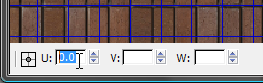
This gives the the horizontal map coordinate for each selected vertex a U value of 0, thereby aligning all the vertices vertically at their origin (0) as shown in the next diagram.
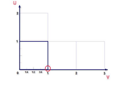
This aligns each selected vertex vertically at a horizontal value of 1.
UVW vertices after alignment
The UVW map now covers the surface of the arch object much better. But as you can see in the window, there remains an obvious problem. The bricks are mapped vertically, whereas they need to be mapped horizontally. To make this change, you need to rotate the mapping by 90 degrees.
Correct the orientation of the bricks:
 (Freeform Mode).
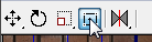
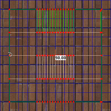
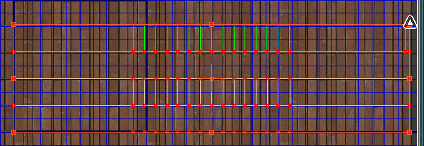
UVW grid after rotation
Now the bricks on the arch are oriented horizontally. Notice, however, that the bricks are still too large for the area they cover.
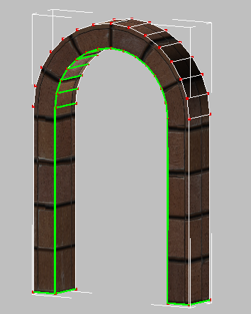
Arch object with bricks oriented horizontally
You need to resize the UVW grid over the map so that the bricks are better distributed.
Align the edges of the bricks and the arch:
Specifically, the current vertical scaling of the bricks means that the edges of bricks are not aligned with the edges of the arch: The UVW grid spans five bricks, when it should span only four.
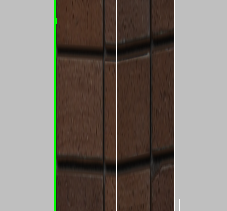
Edges of bricks not aligned with the vertical edges of the arch
UVW grid resized vertically to cover four rows of bricks, one row per face
Now the edges of the bricks and the edges of the arch line up.
Increase the number of bricks along the length of the arch:
zoom out and  pan so you can see all of
the brick-soldier-diff.jpg image.
pan so you can see all of
the brick-soldier-diff.jpg image.
Now the brick-soldier-diff.jpg is tiled twice in each direction.
Zoom out and pan again so you can see all
of the brick-soldier-diff.jpg tiles.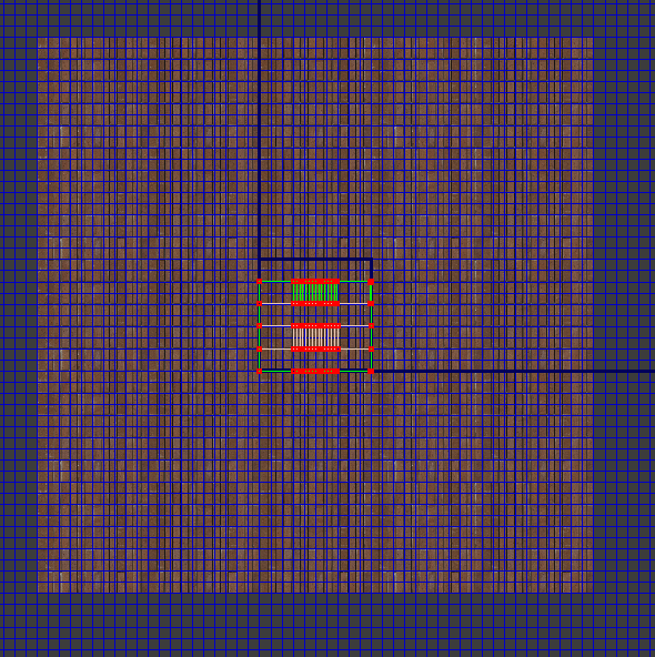
Two image tiles surround the UVW grid in every direction
 Region zoom in again so
you can clearly see the UVW grid and the right edge of the bricks
map.
Region zoom in again so
you can clearly see the UVW grid and the right edge of the bricks
map.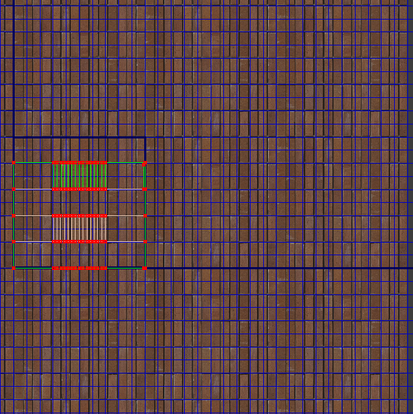
(Freeform Mode). Make sure
all the vertices are still selected, then Shift+drag
the top-right corner vertex all the way to the right-most edge of
the map. 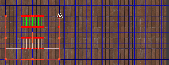
Shift+drag the top right corner of the UVW grid to resize it horizontally
Because the UVW guides have been stretched horizontally to cover three map tiles (from 0 to 3 along the U axis), now three times as many bricks are mapped along the length of the arch.
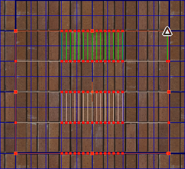
Correct the bulging appearance of bricks at the top of the arch:
If you look closely at the top of the arch, you can see that the bricks appear to bulge out.
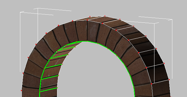
Bricks in arch show deformation
This deformation is because the number of divisions in the arch object’s polygon mesh does not match the number of bricks mapped onto them.
 (Zoom Extents) to zoom in
to the UVW guides, then select only those vertices
in the center that correspond to the top of the arch.
(Zoom Extents) to zoom in
to the UVW guides, then select only those vertices
in the center that correspond to the top of the arch.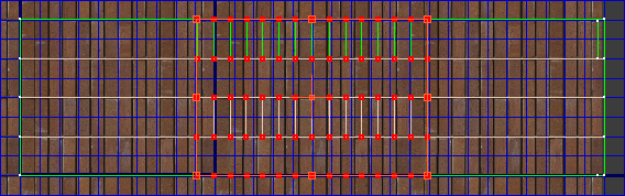
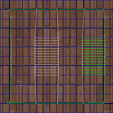
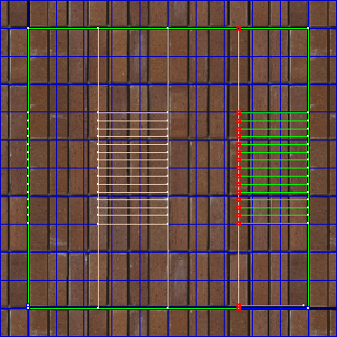
UVW grid with arch vertices selected
There are 14 divisions in the polygon mesh that define the arch, but there are 16 bricks in the underlying map. You need to resize the UVW guides so that the mesh divisions match the number of bricks in the map.
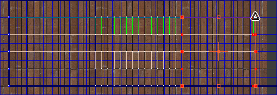
 Freeform tool still active, Shift+drag the top-left corner vertex
of the selection to the right by one brick.
Freeform tool still active, Shift+drag the top-left corner vertex
of the selection to the right by one brick.
The number of arch polygons now matches the number of bricks in the map.
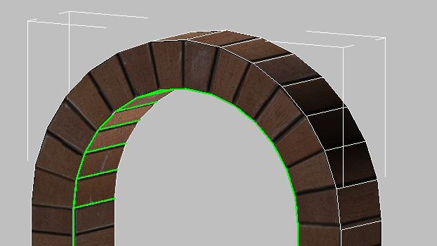
Bricks at the top of the arch no longer appear to bulge.
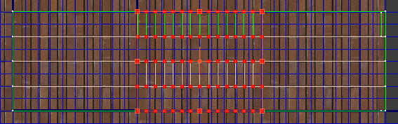
Correct the scaling of bricks in the column:
If you look at the whole archway, you can see that the fix you just made to the top of the arch, makes the bricks at the top appear larger than the bricks in the two columns.
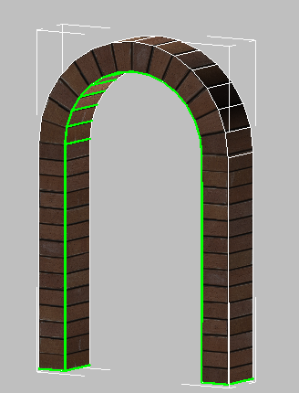
Arch bricks are larger than the column bricks.
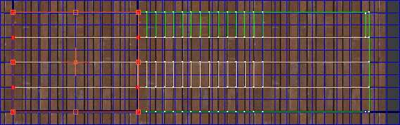
select only the vertices that
correspond to the left-hand column of the arch (which is on the
right in the Edit UVWs window and the viewport).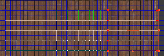
Left column vertices
Left column after being resized two bricks to the left
All bricks mapped to the arch object, both on the columns and the arch, now appear to be equal in size. The result is a properly mapped archway, with the bitmap convincingly following the contours of the object’s geometry.

Arch object with bricks of equal size
Close the Edit UVWs dialog
and on the modifier stack, click Vertex to exit the Vertex sub-object
level, then click any empty part of the viewport to deselect the
arch.
 Minimize the Orthographic
viewport.
Minimize the Orthographic
viewport.
 (Render Production) to render
your work.
(Render Production) to render
your work.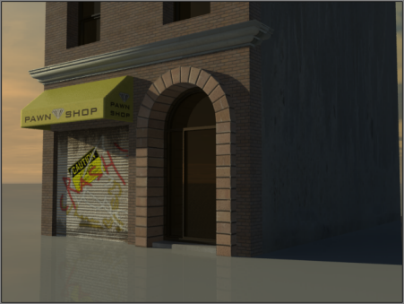
Rendered view of brick material mapped to the pawnshop entrance
In this tutorial, you learned how to use the Unwrap UVW modifier combined with a spline object to map a material onto a curved object. You also learned how to manipulate the object’s UVW lattice in the Edit UVWs dialog to specify how the material’s bitmap image is projected onto the target surface.


