In this lesson, you choose a brick material to map to the building arch, and specify the Unwrap UVW modifier as the mapping method. Then you create a spline object and use it as a guide to the mapping process.
 (Open File), navigate to \scenes\materials_and_mapping\spline_mapping\ and
open splinemap_start.max.
(Open File), navigate to \scenes\materials_and_mapping\spline_mapping\ and
open splinemap_start.max.
Choose the material and apply the mapping method:
 Maximize the Orthographic
viewport and
Maximize the Orthographic
viewport and  select the Arch-Door object.
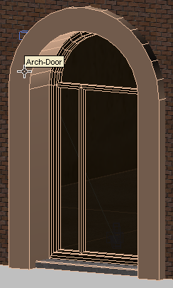
Arch door object with no material applied
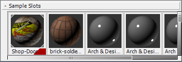
 Slate Material Editor. Locate
the Sample Slots group.
Slate Material Editor. Locate
the Sample Slots group.
A material called brick-soldier has already been prepared for the arch object.
 Sample
Slots group into the active View. In the Instance (Copy) Material
dialog, make sure Instance is chosen, and then click OK.
Sample
Slots group into the active View. In the Instance (Copy) Material
dialog, make sure Instance is chosen, and then click OK.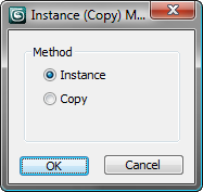
 (Assign Material To Selection).
Also click to turn on
(Assign Material To Selection).
Also click to turn on  (Show Map In Viewport).
The arch turns a dark gray. It shows no further detail because no mapping coordinates have yet been specified for the Arch-Door object.
 Close the Slate Material
Editor.
Close the Slate Material
Editor.
Assign mapping coordinates (a first approximation):
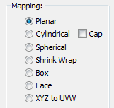
The common way to assign mapping coordinates is to use a UVW Map modifier, but if you look at the various options this modifier has for orienting a map (Planar, Cylindrical, Spherical, Shrink Wrap, Box, Face, and XYZ To UVW), you can see that none of them corresponds to the curved shape of the arch.
 Modify panel. From the Modifier
List, choose Unwrap UVW.
Modify panel. From the Modifier
List, choose Unwrap UVW.
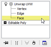
Unwrap UVW is often used to map images onto complex objects. Unwrap UVW is better equipped to handle mapping of complex geometry, because it breaks that geometry into sections, and applies planar mapping to each section.
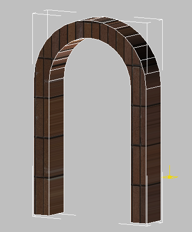
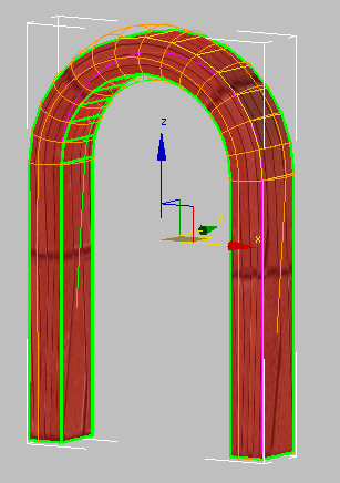
Arch object with brick material mapped to its surface
At this level, you can map the brick material onto each selected face of an object.
select a face on the arch
object.
A yellow gizmo displays, representing a planar projection of brick material onto the selected face.
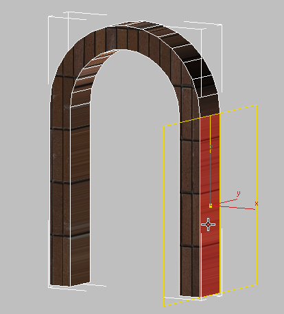
Planar projection of brick material onto an arch face
Select another face on the
arch object.
Notice how the yellow gizmo resets onto the newly selected face.
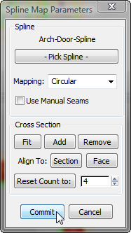
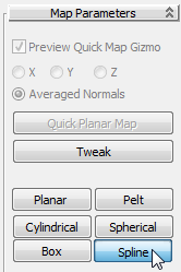
On the Map Parameters rollout, there are a number of controls available that can help you use Unwrap UVW to map specific types of objects. Some of these are similar to the UVW Map options. The Cylinder button, for example, displays controls used to map materials onto cylindrical objects, such as a human arm or a lamp post. Others have more special purposes: You can use the Pelt button to map a material onto fabric such as a pair of trousers, or a curtain.
In this scene, you will use the Spline option, which is useful for mapping curved objects with a cylindrical or square cross-section such as a snake, or a ventilation duct.
Before you use this option, you will create the spline object itself.
Create the spline shape to use as a map path:
The spline you create needs to be centered in the arch object. You could use the Line tool or the Rectangle tool to draw the spline, but you would need to enter the precise arch object coordinate values to do so. A more convenient alternative is to derive the spline from the existing object geometry.
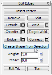
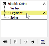
 (Edge) to go to the Edge
sub-object level.
(Edge) to go to the Edge
sub-object level.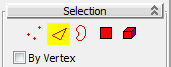
Click and Ctrl+click to select all the outer
edges of the arch object.
Be sure to leave the bottom and inside edges unselected.
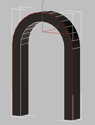
Arch object with all outer edges selected
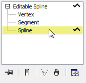
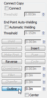
Curve Name box, name
the shape Arch-Door-Spline, make sure Shape
Type is set to Smooth, then click OK.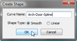
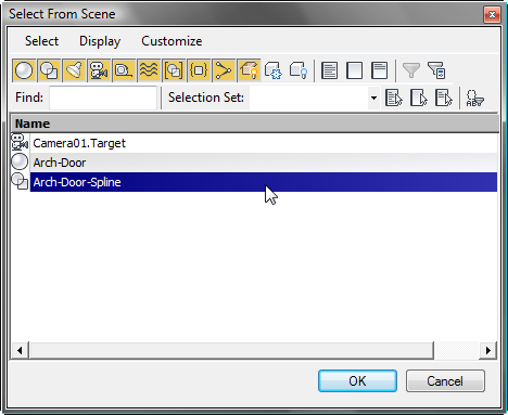
 (Edge) again to exit the
Edge sub-object level, then press H to
open the Select From Scene dialog.
(Edge) again to exit the
Edge sub-object level, then press H to
open the Select From Scene dialog.
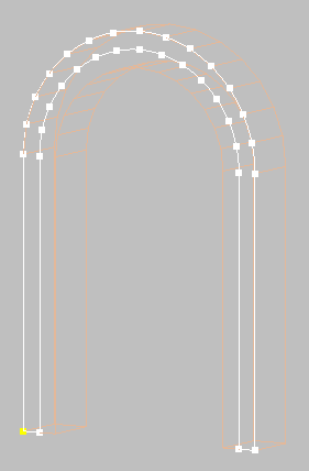
Outline spline centered on the front face of the arch object
The outline spline position does not have to be perfectly centered: You will align it more precisely in a moment.
Click and Ctrl+click to select the line segments
at the base of the arch (they connect the original spline to the
outline spline), then press Delete.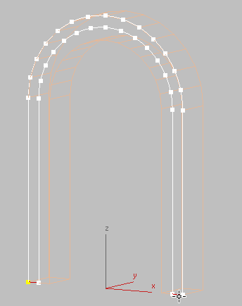
Spline segments at the base of each arch column
Align the spline with the arch:
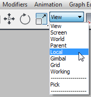
 (Align), and then click
the Arch-Door object.
Align Position (Local)
group, turn off X Position and Y Position, turn on Z Position, and
in both the Current Object and Target Object subgroups, choose Center.
Click OK.
(Align), and then click
the Arch-Door object.
Align Position (Local)
group, turn off X Position and Y Position, turn on Z Position, and
in both the Current Object and Target Object subgroups, choose Center.
Click OK.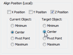
The spline is now properly placed in the center of the Arch-Door object, ready to be used as a guide to map the brick material.
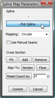
Apply the spline as a guide for the mapping:
Select the Arch-Door object.
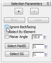
If you leave Ignore Backfacing turned on, only the polygons facing you in the viewport will be included in a selection. Polygons hidden on the other side of the model will remain unselected.
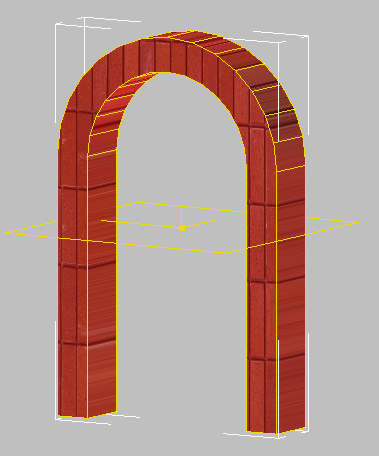
Arch faces selected
The arch object is enveloped by a cage gizmo, which shows the outline and cross sections of the mapping.
Arch object enveloped by the cage gizmo
Now you need to correct the base of the cage gizmo, which is too narrow for the arch geometry.
 Orbit the viewport until
you can see the two unselected faces at the base of the arch.
Orbit the viewport until
you can see the two unselected faces at the base of the arch.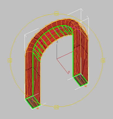
Bottom of arch, showing that the cage gizmo is too narrow
 (Select And Uniform Scale),
For each base of the arch, click to select the base of the gizmo,
then drag the Scale gizmo along its Y axis until the cage is at
least as wide as each face at the base of the arch.
(Select And Uniform Scale),
For each base of the arch, click to select the base of the gizmo,
then drag the Scale gizmo along its Y axis until the cage is at
least as wide as each face at the base of the arch.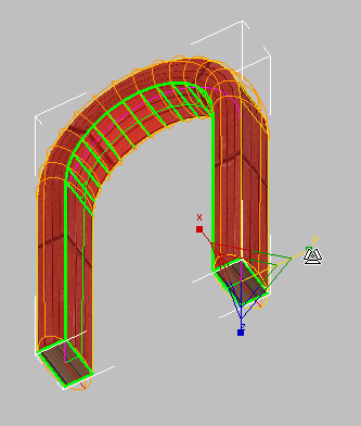
Cage gizmo after resizing each base
You do not need to be precise at this point: In the next lesson, you will specify the cage more precisely by using the Unwrap UVW controls.