In this lesson, you will learn how to rotate the wheels by an amount that corresponds to the distance travelled by the car model.
Let’s start by taking a look at the trigonometry involved in calculating the wheel rotation.
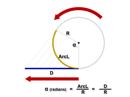
In any circular object, the amount of rotation (a) is defined by the radius of the circle and the arc length encompassed by the a angle. That amount of rotation (a) expressed in radians, is equal to the arc length, divided by the radius of the circle (arc length / R), where:
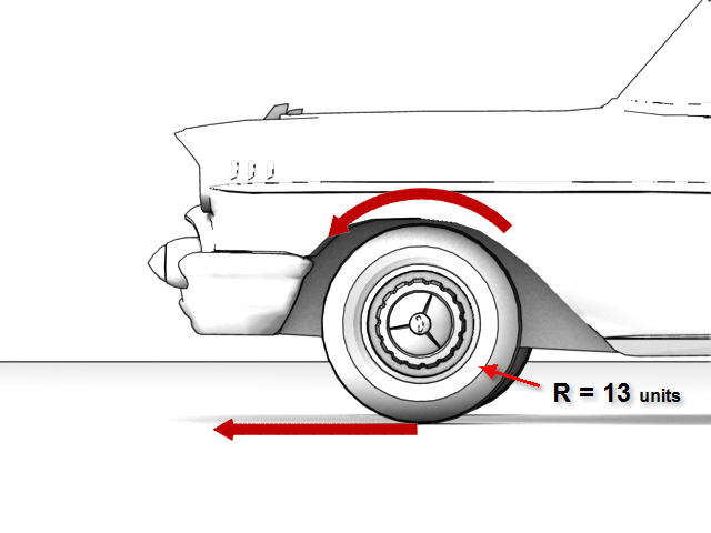
Therefore, the wheel rotation calculation (arc length / R) becomes distance / 13. Whereas the radius of the wheel is constant and equal to 13, the distance travelled is variable.
Rotate the wheels (in World X coordinates):
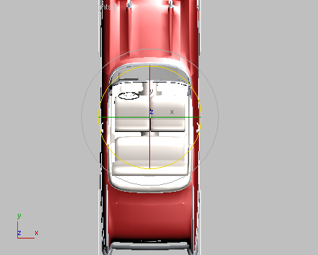
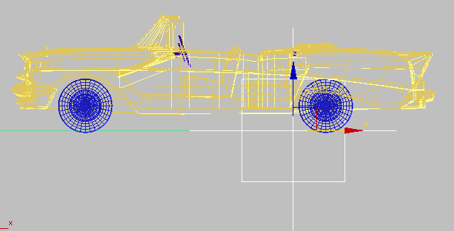
The car is currently oriented on the World X axis: you will begin working in this coordinate system.
 Position (2nd) Position XYZ X Position.
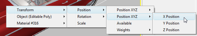
A rubber band shows the link you are about to make between your two selected objects.
Rotation (2nd) Euler XYZ Z Rotation.
The Parameter Wiring #1 dialog opens. You use this dialog to set up one and two-way control relationships between objects. The position and rotation of the two objects you just selected to affect one another are highlighted.
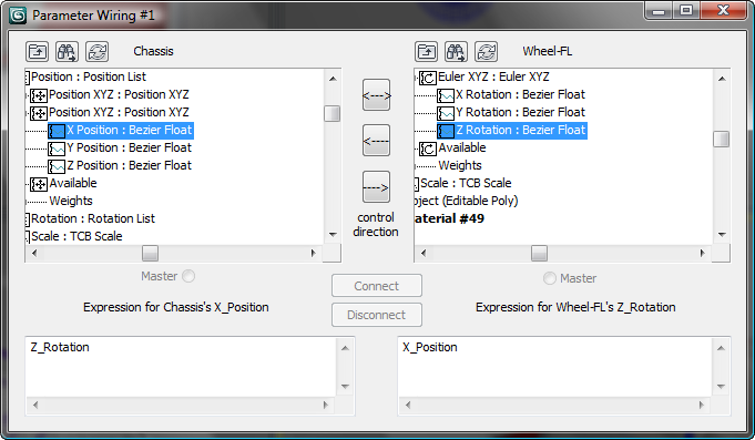
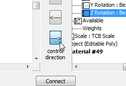
This ensures that the Chassis X position is controlling the Wheel-FL Z rotation and not the other way around.
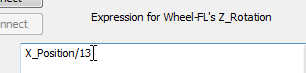
The bottom-right corner of the Parameter Wiring dialog displays the wheel object Expressions panel. It shows the distance travelled as X_Position.
The expression should now read X_Position/13, the distance divided by the radius of the wheel.
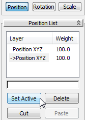
Notice how the front-left wheel does not rotate. Even though you added a position list controller to the car and wheel, the first controller in the list (the one that ensures the parent/child “lock”) is still active. You need to make the second position controller (the one used in the wiring process) the active one.
 Motion panel PRS Parameters rollout,
click the Position button at the bottom of the rollout.
Motion panel PRS Parameters rollout,
click the Position button at the bottom of the rollout.
The wheel now rotates, and at the correct rate, but its motion is backward.
Because the wheels were mirrored, the wheels on the right side of the car do not need the minus sign added to their expression, whereas those on the left side do.
 Close all the Parameter
Wiring dialogs.
Close all the Parameter
Wiring dialogs.
Add subcontrollers for Y rotation:
In the previous procedure, you learned how to add controllers that determine car wheel rotation for the length of distance travelled by the model along the World X axis. However, if you tried to rotate the car in any way, wheel rotation would be reduced or stop altogether. You therefore need to add controllers that account for the car’s displacement in a Y direction.
The car is now oriented on the World Y axis, so you will begin working in this coordinate system.
 Orbit the Perspective viewport
until you can see the front left side of the car.
Orbit the Perspective viewport
until you can see the front left side of the car.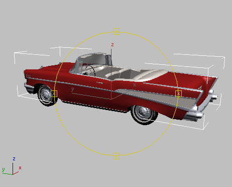
 Move the car forward and
backward on the Y axis. Notice that the wheels do not rotate.
Move the car forward and
backward on the Y axis. Notice that the wheels do not rotate.
To get the wheels rotating, you will need additional animation controllers, ones that will control the car’s displacement in the Y direction. You will add these as sub-controllers, so you do not overwrite the controllers already in place.
$.rotation.controller.Available.controller = Euler_XYZ ()
Be sure not to include the line’s carriage return when you make your selection. Press Ctrl+C to copy this line to memory.
If you are not continuing from the previous lesson, this line will not be available from the Open Listener window. If this is the case, copy the line from the text of this tutorial.
Close the MAXScript Listener
window, then  select the front left wheel
(Wheel-FL).
Motion panel PRS Parameters rollout,
make sure that the Rotation button is active, Then on the Rotation
List rollout, verify that a new sub-controller has been added to
the rotation list (there should be 3 in all).
select the front left wheel
(Wheel-FL).
Motion panel PRS Parameters rollout,
make sure that the Rotation button is active, Then on the Rotation
List rollout, verify that a new sub-controller has been added to
the rotation list (there should be 3 in all).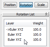
Select another wheel and
repeat steps 7 to 9 until all four wheels have four Euler XYZ tracks
in their respective rotation lists.
Rotate the wheels (in World Y coordinates):
Position (2nd) Position XYZ Y Position.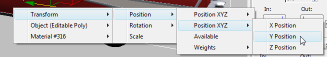
Rotation (3rd) Euler XYZ Z Rotation.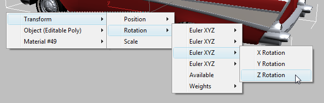
The expression for the left-hand wheel should be Y_Position/13
Close the Parameter Wiring
dialogs.
 rotate the car so that it
is not pointing horizontally or vertically.
(Select And Move), then set
the coordinate system to Local.
rotate the car so that it
is not pointing horizontally or vertically.
(Select And Move), then set
the coordinate system to Local.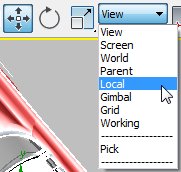
Rotate the wheels (under a path constraint):
In the previous procedure, you learned how to add controllers that rotate the car wheels for any distance of travel in World X and Y space. The wheels will therefore rotate properly when you manually move the car around the scene in any direction.
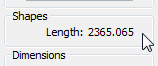
However, you would most often animate motion of a car by placing it on a predefined path using the Path constraint. This type of animation requires a different expression.
This new expression uses the same formula (distance divided by radius) as the ones you have been using, but while the radius of the wheel remains constant, the distance travelled is calculated differently.
 open the file car_rig_03.max.
Selection Sets list, choose Car
Path.
open the file car_rig_03.max.
Selection Sets list, choose Car
Path.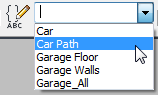
Helpers Point.
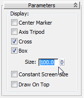
This increases the size of the helper gizmo and makes it easier to select in the scene.
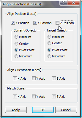
 (Align), then in any viewport,
select the car body.
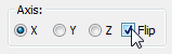
Align Position group,
make sure X Position and Y Position are on and Z position is off.
(Align), then in any viewport,
select the car body.
Align Position group,
make sure X Position and Y Position are on and Z position is off.
Point helper moved to left of rear axle
The Point helper location you have specified will become the pivot point of the car when the front wheels turn.
Name And Color rollout, rename the helper Dummy_CAR.
 (Select And Link), then
in the Front viewport, click the car body and drag to the Point
helper. This makes the car body the child of the Point helper.
(Select And Link), then
in the Front viewport, click the car body and drag to the Point
helper. This makes the car body the child of the Point helper.
 (Select Object) to exit
link mode.
(Select Object) to exit
link mode.
 (Zoom Extents) to view the entire
parking lot.
Camera_Wall-E.
(Zoom Extents) to view the entire
parking lot.
Camera_Wall-E.
Animate the dummy by constraining it to a path:
Constraints Path Constraint.
The helper and the linked car are repositioned at the start of the path.
The car’s orientation remains constant throughout the animation.
Motion panel Path Parameter rollout Path Options group,
turn on Follow.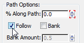
Car motion is improved, but at the last frame the car points at an awkward angle. This is a common behavior to paths based on a NURBS curve. You will now correct this problem.
 (Auto Key).
Motion panel Path Parameters rollout Path Options group % Along Path box, type 99.9 and
then press Enter.
(Auto Key).
Motion panel Path Parameters rollout Path Options group % Along Path box, type 99.9 and
then press Enter.
 (Auto Key) and scrub the
animation.
(Auto Key) and scrub the
animation.
The car is properly oriented on the path, but the wheels no longer rotate. This is because the expression that defined the wheel rotation you formulated earlier no longer applies. The distance travelled by the car was dependent on the X and Y displacement in the World coordinate system. Displacement is now tied to the length of the path and the percentage of the path that the car has travelled. You must therefore modify the expression to reflect this change.
Wire wheel rotation to a path:
 Utilities panel.
Position Path Constraint Percent.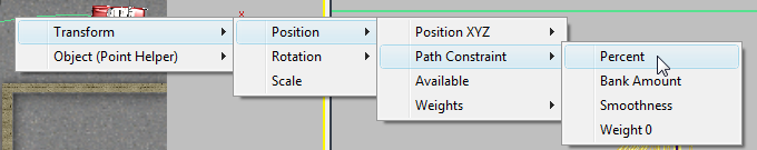
Rotation (4th) Euler Rotation Z Rotation.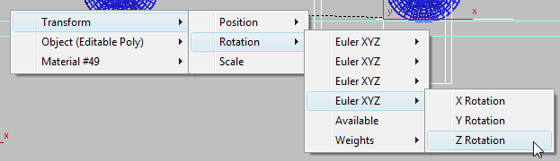
 (Time Configuration) and
in the Time Configuration dialog Time Display group, choose FRAME:TICKS.
(Time Configuration) and
in the Time Configuration dialog Time Display group, choose FRAME:TICKS.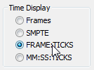
Remember to add a minus sign (-) operator to the expression of the wheels on the right side of the model so they don’t rotate in the opposite direction.


