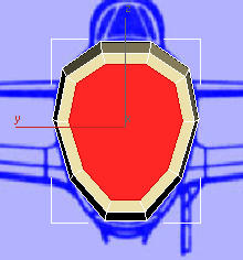
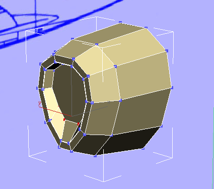
At the front of the cowl, the cover of the air intake is recessed, and has a rounded shape. You don’t need to make the model as detailed as an actual airplane would be, but these steps give the general look of the front of the plane.
This makes it easier to see the polygons with which you’re working.
 Polygons
panel, click
Polygons
panel, click  (Inset). In the Perspective
viewport, drag downward to reduce the size of the front polygon, and
add polygons around it.
(Inset). In the Perspective
viewport, drag downward to reduce the size of the front polygon, and
add polygons around it.
You can also see this change in the Left viewport.
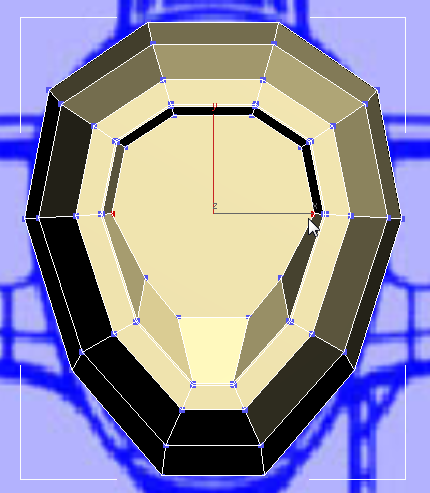
Polygons panel, click  (Bevel). In the Perspective
viewport, drag downward to recess the central polygon.
(Bevel). In the Perspective
viewport, drag downward to recess the central polygon.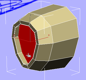
Release the mouse, then drag it downward again a little bit, to taper the inside of the recess. This change is easier to see in the Left viewport.
As for most of the P-47 model, exact distances don’t matter here: The important thing is the overall look.
Even with X-Ray display, it is a little hard to see details of the blueprint image.
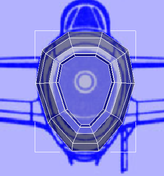
Here is the image without the geometry in front of it:

(If you like, you can
also choose Rendering View
Image File, and then open \sceneassets\images\p47_front.jpg to
see the full-size version of this image.)
As the blueprint image shows, there is a circular area within the recess: This is the intake for air to help cool the engine. The air intake for the engine’s combustion is a pipe located below the circular area.
Polygon Modeling panel, click  (Edge) to go to the Edge
sub-object level.
(Edge) to go to the Edge
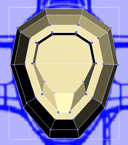
sub-object level.  Click to select the center
edge at the bottom of the recess.
Click to select the center
edge at the bottom of the recess.
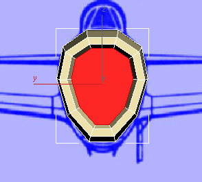
 Move the edge up until it
is just below the circular border.
Move the edge up until it
is just below the circular border.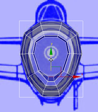
 Scale the edge out a bit
along the X axis so the outline of the intake becomes a bit rounder.
Scale the edge out a bit
along the X axis so the outline of the intake becomes a bit rounder.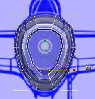
Polygon Modeling panel, click  (Vertex) to go to the Vertex
sub-object level. Click and Ctrl+click to select the four vertices at
the lower edge of the inner portion of the recess.
(Vertex) to go to the Vertex
sub-object level. Click and Ctrl+click to select the four vertices at
the lower edge of the inner portion of the recess.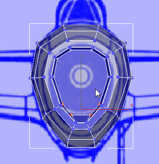
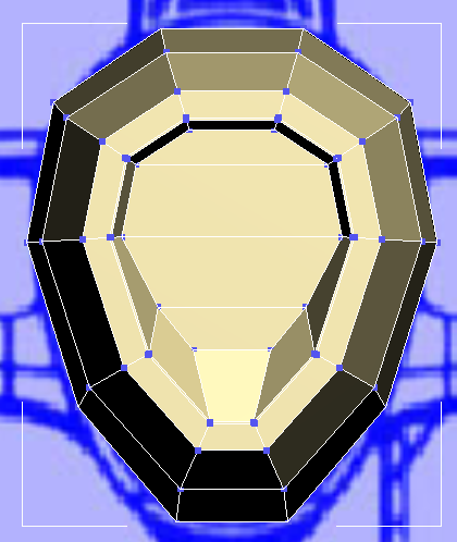
Move the vertices up along
the Y axis to make the cooling intake even more rounded.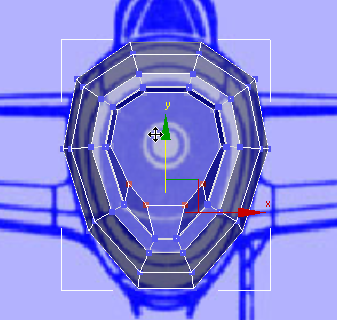
If you activate the Perspective viewport and press Alt+X to turn off X-Ray display, you can get a better view of the work you’ve just done.
The front of the airplane is nearly done, for the time being. But because of the way 3ds Max constructed the cylinder that was the origin of this model, the intake face is a 10-sided polygon. As we mentioned earlier, it is best if the mesh consists of consistently quadrangular polygons: These work much better with smoothing and (if you are creating a character) with skin deformation. So to complete the air intake, you divide the large 10-sided polygon into smaller quadrangular polygons.
 Zoom in a bit so the geometry
is easier to see.
Zoom in a bit so the geometry
is easier to see.
Loops panel, click  (Connect).
It is hard to see the connecting edge until you click elsewhere in the viewport to deselect the initial vertices.
Now the original 10-sided polygon is divided into four polygons, and each of the new polygons has only four sides.


