You build the P-47 Thunderbolt from scratch, but use planes with “blueprint” images to guide your work. The airplane will consist of just two objects: The fuselage with its wings and other details, and the canopy that goes over the cockpit.
 (Open File), navigate to
the \scenes\modeling\p47 folder,
and open p47_start.max.
(Open File), navigate to
the \scenes\modeling\p47 folder,
and open p47_start.max.The scene contains three planes that show side, front, and top elevations of the airplane: a “virtual studio” as described in Pointers on Setting Up a “Virtual Studio”.
Optimize bitmap display in viewports:
 Preferences.
Configure
Driver.
Preferences.
Configure
Driver.
3ds Max opens the configuration dialog for the graphics driver you are using (Software, OpenGL, or Direct3D).
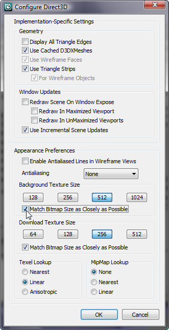
Configuration dialog for the Direct3D driver
Bitmap configuration changes do not take effect immediately: You always have to restart 3ds Max.
If you did not have to change the Match Bitmap Size setting, you can continue without restarting 3ds Max.
 (Maximize Viewport Toggle)
to display all four viewports.
(Maximize Viewport Toggle)
to display all four viewports.
 (Zoom Extents).
 (Region Zoom) to get a better
view of the front of the airplane.
(Region Zoom) to get a better
view of the front of the airplane.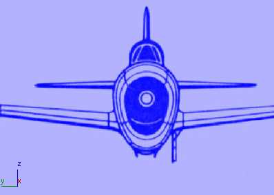
Create a cylinder to begin the engine cowl:
 Create panel, activate
  (Geometry), then on the
Object Type rollout, click Cylinder.
(Geometry), then on the
Object Type rollout, click Cylinder.
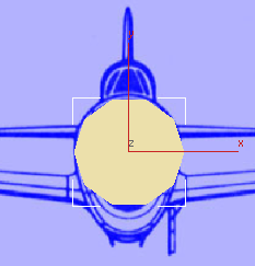
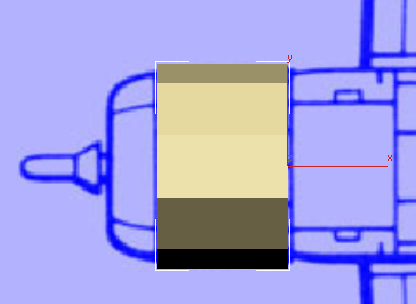
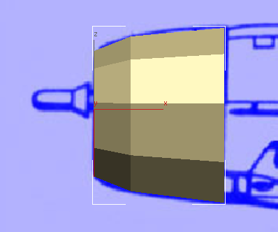
 (Select And Move). In the
Left viewport, move the cylinder so it is well centered on the image
of the airplane. In the Top viewport, move it forward so its rear
edge coincides with the rear edge of the engine cowl.
(Select And Move). In the
Left viewport, move the cylinder so it is well centered on the image
of the airplane. In the Top viewport, move it forward so its rear
edge coincides with the rear edge of the engine cowl.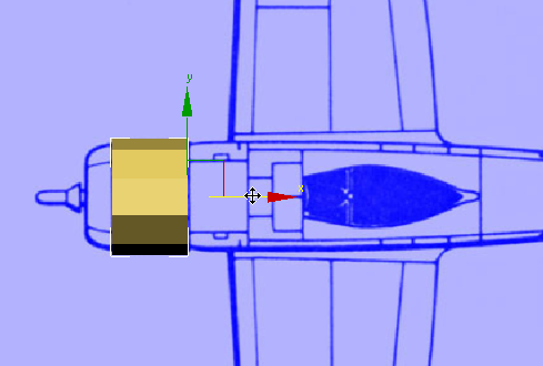
 zoom and
  pan a particular viewport
to get a better view of the geometry and the blueprint image. In
general, we mention view changes when they are particularly important
or useful, but you might want to change the view more often than
we indicate. This is quite all right.
pan a particular viewport
to get a better view of the geometry and the blueprint image. In
general, we mention view changes when they are particularly important
or useful, but you might want to change the view more often than
we indicate. This is quite all right.
 Modify panel, and apply
an FFD 3x3x3 modifier to the cylinder.
Modify panel, and apply
an FFD 3x3x3 modifier to the cylinder.
FFD stands for “free-form deformation.” This modifier lets you adjust the shape of the cylinder, using a 3x3x3 array of control points.
 (the plus-sign icon) to open
the FFD 3x3x3 modifier hierachy. Click Control Points to highlight that
sub-object level.
(the plus-sign icon) to open
the FFD 3x3x3 modifier hierachy. Click Control Points to highlight that
sub-object level.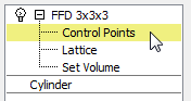
 move them down so they coincide
with the bottom of the fuselage.
move them down so they coincide
with the bottom of the fuselage.  Scale them along the X axis
so they are a bit closer together.
Scale them along the X axis
so they are a bit closer together.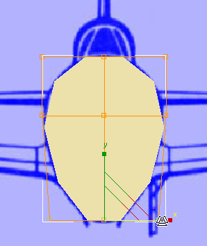
Scale them out a bit along
the X axis, then move them up a bit along
the Y axis.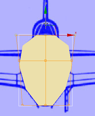
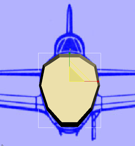
You now have a good cross-section of the cowl at the front of the fuselage. In the next procedure, you refine its shape along the length of the airplane.
Taper the profile of the cowl:
FFD 2x2x2.
You will use this additional free-form deformation modifier to give some taper to the nose of the airplane.
(the plus-sign icon) to open
the FFD 2x2x2 modifier hierachy. Click Control Points to highlight that
sub-object level.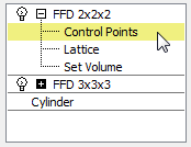
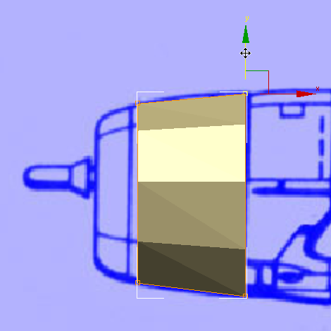
move the points to follow
the taper of the image. Do the same for the lower trailing edge
of the cowl.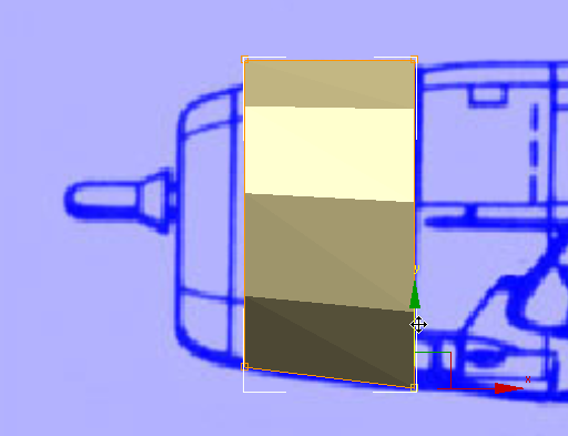
scale them down a bit along
the Y axis to taper the cowl in that dimension as well. so it matches
the blueprint image.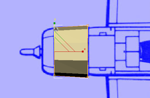
The changes you make in the Front and Top viewports also appear in the Left viewport.
Convert To Editable Poly.
By converting the cylinder to an Editable Poly object, you lose the specific Cylinder and FFD modifier controls, but you gain access to the rich set of Editable Poly sub-object controls.
 (Graphite Modeling Tools (Open)).
 expand/minimize icon until
the full ribbon is visible.
Graphite Modeling Tools tab Polygon Modeling panel,
click
expand/minimize icon until
the full ribbon is visible.
Graphite Modeling Tools tab Polygon Modeling panel,
click  (Polygon) to go to the Polygon
sub-object level.
(Polygon) to go to the Polygon
sub-object level.
 click to select the large
polygon at the front of the cowl.
click to select the large
polygon at the front of the cowl.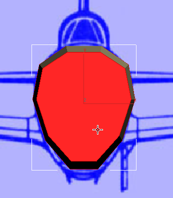
Polygons panel, click  (Bevel).
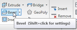
The Bevel tool does two things: It extrudes a selection, and then lets you scale the size of the extrusion.
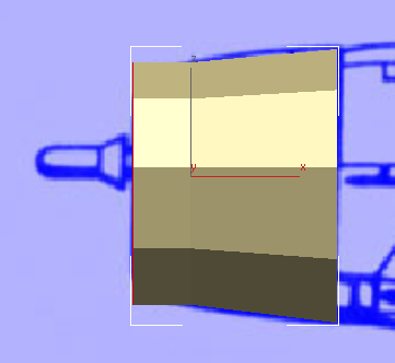
Release the mouse, then drag downward to scale the polygon so it tapers as the blueprint image shows.
The curve of the cowl is subtler than the model we have so far, but you will fix that later on.


