The portion of the tail that rises above the fuselage is technically known as the “vertical stabilizer.”
Begin extruding the vertical stabilizer:
 (Polygon) sub-object level.
 click and Ctrl+click to select the two faces
on the top of the fuselage, from which you will “grow” the upper
part of the tail.
click and Ctrl+click to select the two faces
on the top of the fuselage, from which you will “grow” the upper
part of the tail.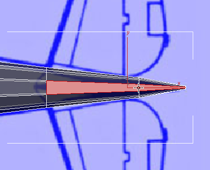
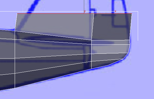
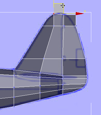
 Extrude these faces upward
as far as the first hinge of the rudder.
Extrude these faces upward
as far as the first hinge of the rudder.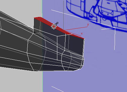
Front view
 Align panel, click
  (Align Y).
3ds Max aligns the two polygons so they are level.
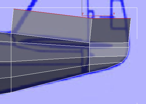
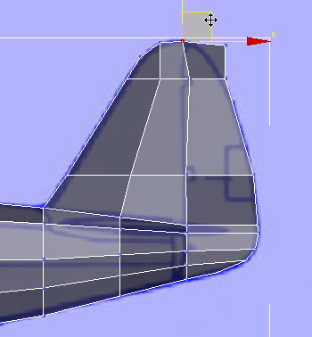
Front view
 scale and
  move the faces along the
X axis to match the outline of the tail to the blueprint image.
move the faces along the
X axis to match the outline of the tail to the blueprint image.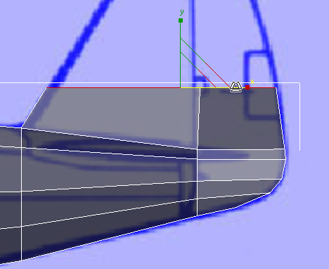
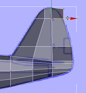
Polygon Modeling panel, click  (Vertex).
region-select the two vertices at
the leading edge of the top of the tail.
(Vertex).
region-select the two vertices at
the leading edge of the top of the tail.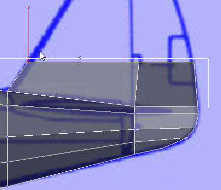
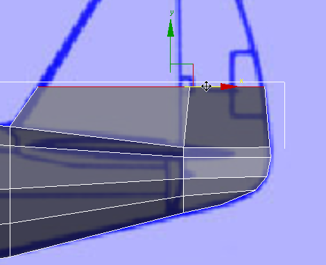
scale these two vertices
along the Y axis to bring them closer together and narrow the width
of the tail.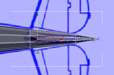
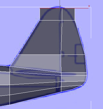
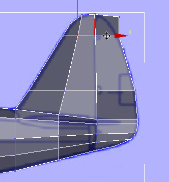
Complete the vertical stabilizer:
region-select the vertices
at the center of the top edge of the tail, and move them along the X axis
to align them with the leading edge of the rudder.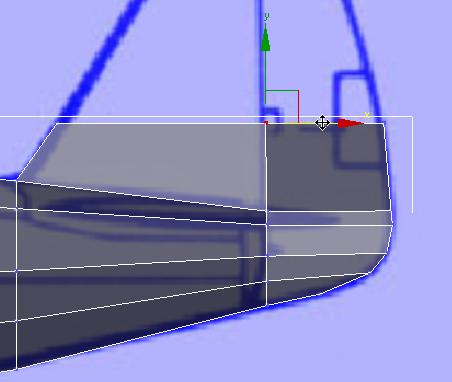
Polygon Modeling panel, click (Polygon).
The two faces on top
of the tail should become the active selection again. If they don’t,
then in the Top or Perspective viewport, click and Ctrl+click to select them.
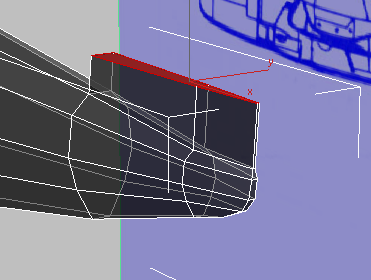
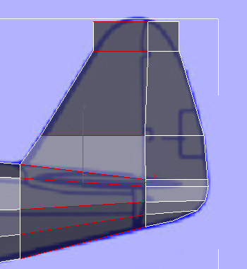
Extrude the faces on the
top of the tail as far as the top of the upper hinge of the rudder.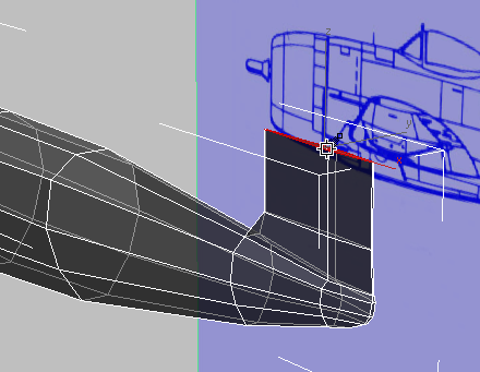
Front view
scale and move the faces in the X
axis to fit the tail outline to the blueprint image.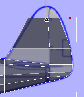
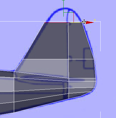
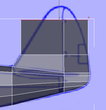
Extrude the tail polygons
a final time, stopping just shy of the top of the tail as shown
in the blueprint images.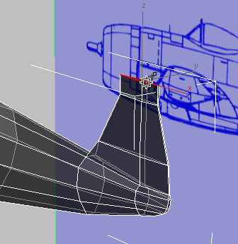
Front view
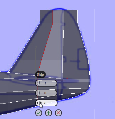
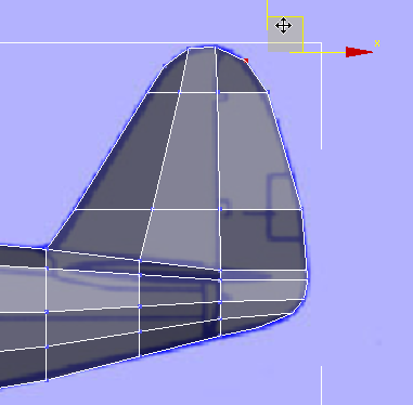
As you did for the bottom portion of the tail, you will move vertices to round the outline of the top of the tail. But to get enough vertices to model the curvature well, first you add another set of edges,
Polygon Modeling panel, click  (Edge).
In the Front viewport, click
to select one of the horizontal edges on the forward, stationary
portion of the tail.
(Edge).
In the Front viewport, click
to select one of the horizontal edges on the forward, stationary
portion of the tail.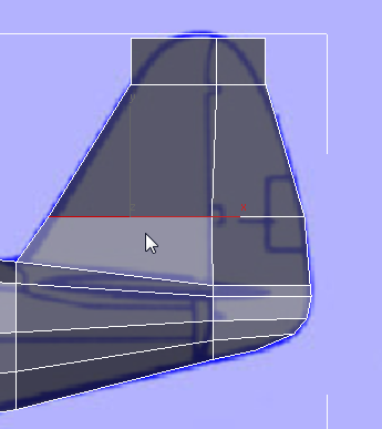
Modify Selection panel, click  (Ring).
3ds Max selects a ring of parallel edges around the forward part of the tail and the corresponding portion of the fuselage.
Loops panel, Shift+click  (Connect).
 (OK).
(Vertex) sub-object level,
then use region-select to select pairs of vertices, and move them to follow the outline
of the tail, as shown in the blueprint image. At this stage, you might
also want to move the vertex pairs in the middle of the tail, to improve
their alignment.
(OK).
(Vertex) sub-object level,
then use region-select to select pairs of vertices, and move them to follow the outline
of the tail, as shown in the blueprint image. At this stage, you might
also want to move the vertex pairs in the middle of the tail, to improve
their alignment.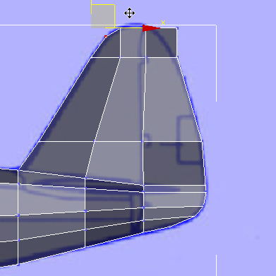
 (Vertex) again to exit the
Vertex sub-object level.
(Vertex) again to exit the
Vertex sub-object level.


