In this lesson, you add more edges to improve the regularity of the fuselage and refine its profile.
Add vertical edges to the fuselage:
 (Zoom Extents Selected)
so you can see all of the fuselage.
(Zoom Extents Selected)
so you can see all of the fuselage.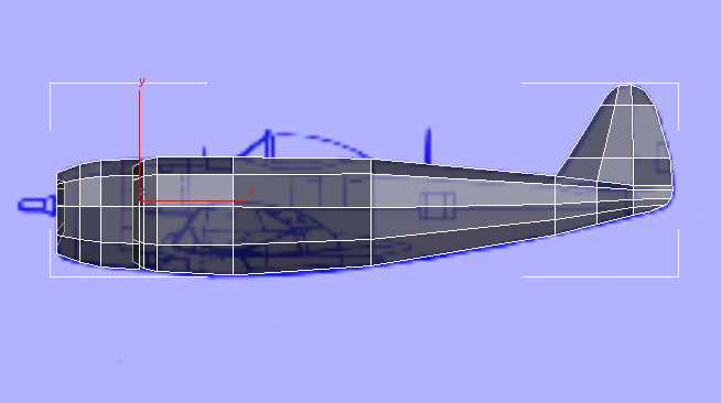
 Polygon Modeling panel, click
  (Edge).
 Select one of the edges
in the portion of the fuselage between the cockpit and the tail.
Select one of the edges
in the portion of the fuselage between the cockpit and the tail.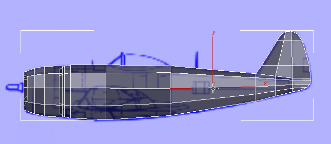
Modify Selection panel, click  (Ring).
3ds Max selects all parallel edges around the circumference of the fuselage.
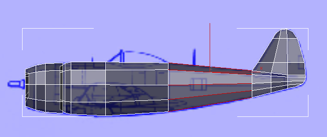
Loops rollout, Shift+click  (Connect).
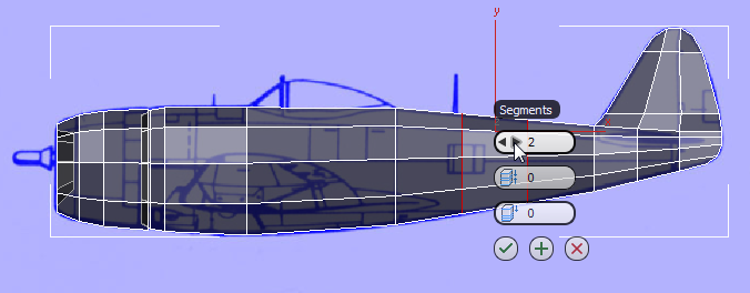
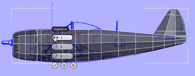
3ds Max displays the
caddy for the Connect tool. For the third setting, Slide, right-click
the spinner arrows to reset the value to 0. Then change
the first setting, Segments, to 2, and then
click  (OK).
(OK).
3ds Max adds two vertical sets of edges, evenly spaced, along the length of the rear of the fuselage. (Setting the Slide value to zero guarantees that the new edge loops are evenly spaced.)
Select one of the horizontal
edges below the cockpit. Click (Ring) again, and then click
Loops panel (Connect).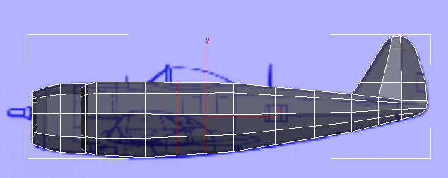
Select one of the horizontal
edges in the section of the fuselage in front of the cockpit. Click (Ring) again, and then Shift+click (Connect). Use the Connect
tool caddy to reduce the number of Segments to 1,
and then click (OK).
3ds Max adds a single set of vertical edges between the front of the cockpit and the rear of the engine cowl.
Adjust the curve of the lower part of the fuselage:
Polygon Modeling panel, click  (Vertex).
 move them along the Y axis
so the bottom outline of the fuselage better follows the curve that
the blueprint image shows.
move them along the Y axis
so the bottom outline of the fuselage better follows the curve that
the blueprint image shows.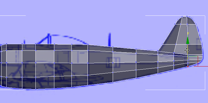
 (Vertex) again to exit the
Vertex sub-object level.
(Vertex) again to exit the
Vertex sub-object level.


