


Complete the Horizontal
Stabilizers
To complete the horizontal stabilizers, you continue extruding and shaping them as you did the vertical stabilizer.
Continue extruding the stabilizers:
 (Extrude), and then drag
to extrude the stabilizer as far as the rectangular flap. Work in
the Front viewport but watch the Top viewport.
(Extrude), and then drag
to extrude the stabilizer as far as the rectangular flap. Work in
the Front viewport but watch the Top viewport.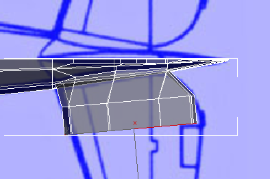
 move and
  scale the faces in their
local Y axis so they match the blueprint image.
scale the faces in their
local Y axis so they match the blueprint image.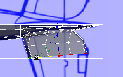
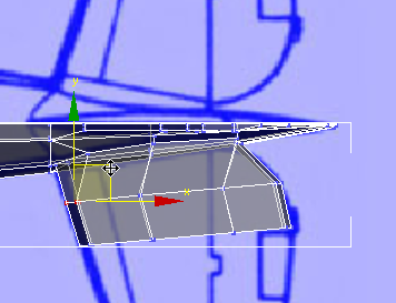
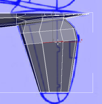
 (Vertex), then in the Top
viewport, move the vertices at the
leading edge of the stabilizer to better match the blueprint image.
(Vertex), then in the Top
viewport, move the vertices at the
leading edge of the stabilizer to better match the blueprint image.
 (Polygon) level, then extrude the stabilizer again,
this time almost to the tip.
(Polygon) level, then extrude the stabilizer again,
this time almost to the tip.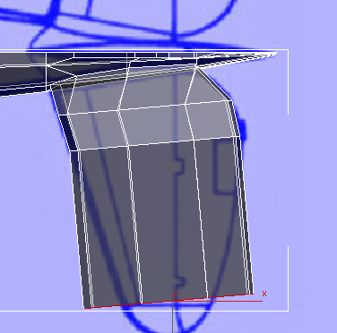
 Align panel, click
  (Align X).
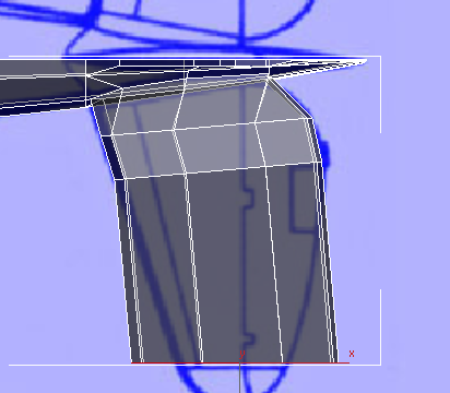
move and scale the faces in their
local Y axis so they match the blueprint image.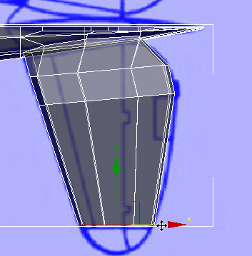
Go to the  (Edge) sub-object level.
  Click to select one of the
longitudinal edges in the widest faces of the stabilizer.
Click to select one of the
longitudinal edges in the widest faces of the stabilizer.
Modify Selection panel, click  (Ring).
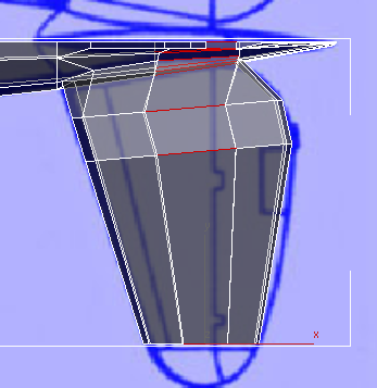
Loops panel, click  (Connect).
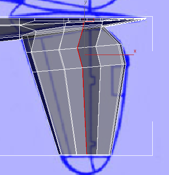
Now the tip of the stabilizer has seven pairs of vertices, which will help you give it shape.
 zoom in on the tip and
  pan so you have a good view
of both the geometry and the blueprint image.
pan so you have a good view
of both the geometry and the blueprint image.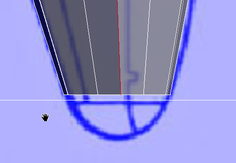
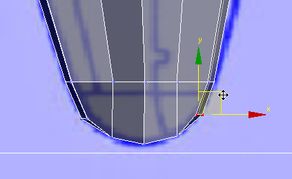
(Polygon) sub-object level,
and extrude the faces again,
almost to the end of the stabilizer in the blueprint image.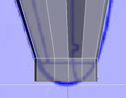
(Vertex) sub-object level,
then use region selection to move vertices so they match
the curve of the tip of the stabilizer.
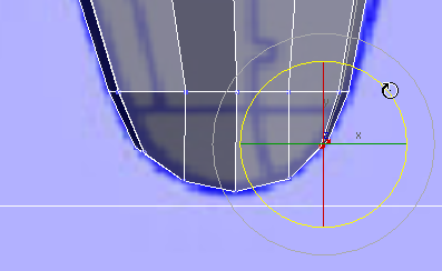
 rotate the vertex pairs
so they follow the contour of the curve.
rotate the vertex pairs
so they follow the contour of the curve.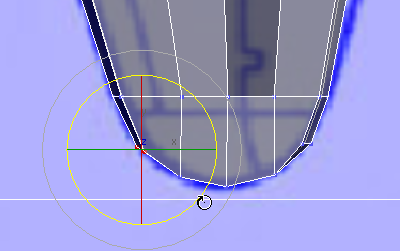
 (Vertex) again to exit the
Vertex sub-object level.
(Vertex) again to exit the
Vertex sub-object level.