


Begin Adding the Horizontal
Stabilizers
The horizontal stabilizers are shaped like small wings, and you use similar methods to model both these airplane parts. Because the horizontal stabilizers and the wings are symmetrical, it helps to split the model in half and use a Symmetry modifier to restore the mesh: This way, you have to model only one stabilizer and one wing; the modifier takes care of the other side of the airplane.
 open \modeling\p47\p47_01.max.
 select the P-47 fuselage
and go to the
select the P-47 fuselage
and go to the  Modify panel.
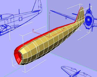
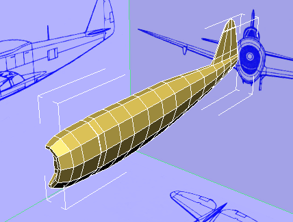
Split the model in half and add a Symmetry modifier:
Select the fuselage. Then
on the ribbon  Polygon
Modeling panel, click
Polygon
Modeling panel, click  (Edge).
Click to select one of the
lateral edges at the very top of the fuselage.
(Edge).
Click to select one of the
lateral edges at the very top of the fuselage.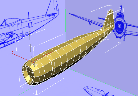
Modify Selection panel, click  (Ring).
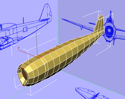
Loops panel, Shift+click  (Connect).
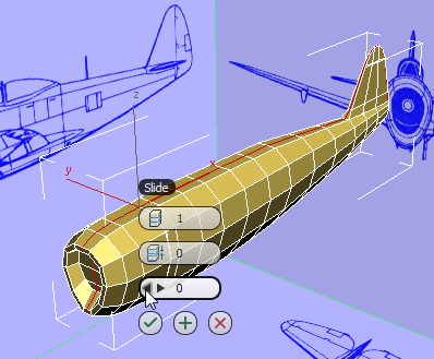
3ds Max displays the
Connect tool caddy. On the caddy, be sure to set Slide (the third
control) to 0 so the new set of edges is perfectly
centered, and then click  (OK).
(OK).
Polygon Modeling panel, click  (Polygon).
Click the viewport at a
distance from the fuselage, to make sure no polygons are selected.
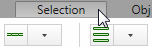
Selection tab By Half panel, make sure that X is the chosen
axis, and then click  (Select).
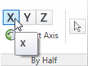
This selects the right half of the P-47 (from the airplane’s point of view).
 (Polygon) to exit the Polygon
sub-object level.
(Polygon) to exit the Polygon
sub-object level.
Modifier List, choose Symmetry.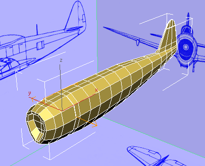
Now the model appears complete again. But the right side is generated by the Symmetry modifier, and changes you make to the left side will be reflected on the other side.
Create the edges from which you will build the stabilizers:
 zoom in to the region where
the stabilizers will be.
zoom in to the region where
the stabilizers will be.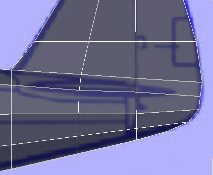
Polygon Modeling panel, click  (Previous Modifier), then
click (Polygon).
(Previous Modifier), then
click (Polygon).
Also on the ribbon Polygon Modeling panel,
click to turn off  (Show End Result). This
makes it a bit easier to see the blueprint image.
(Show End Result). This
makes it a bit easier to see the blueprint image.
Modify panel Subdivision Surface
rollout, turn off Show Cage.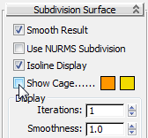
The cage display can be useful when you work with smoothing, but for the time being, it just makes it harder to see the plain geometry.
Edit panel, turn on  (Cut).
In this step, you create free-standing vertices to round the leading and trailing edges of the stabilizer: In general, a model should not have free-standing vertices, and in a moment you will add edges to connect these vertices to other vertices.
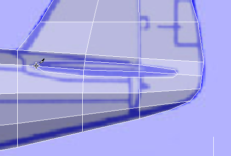
Cut tool again to create
edges that join the free-standing vertices to the corner vertices
of the neighboring faces. This ensures that the mesh still has all
quadrangular faces.
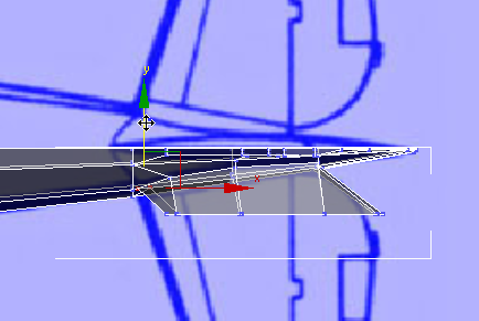
Begin to extrude the stabilizers:
Click and Ctrl+click to select the faces at
the base of the stabilizer.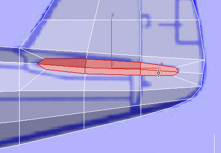
 (Maximize Viewport Toggle)
to display all four viewports.
Polygons rollout, Shift+click
(Maximize Viewport Toggle)
to display all four viewports.
Polygons rollout, Shift+click  (Extrude). Use the caddys
Height control to extrude the faces by a value of about 20.0.
Watch your work in the Perspective and Top viewports.
(Extrude). Use the caddys
Height control to extrude the faces by a value of about 20.0.
Watch your work in the Perspective and Top viewports.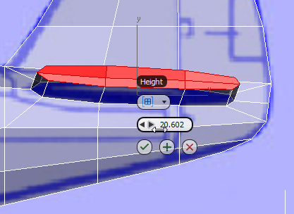
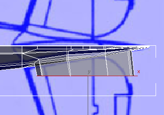
Top view
(OK).
Align panel, click  (Align X).
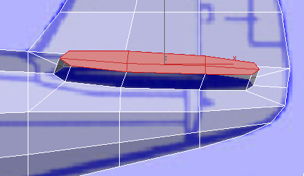
Top view
As you can see, there is a discrepancy between the side and top blueprint images. This is not unusual, especially when one of the drawings is foreshortened as the side image is. In the next couple of steps, you will adjust vertices to better match the top image, which is the more accurate one.
 (Vertex) sub-object level.
  Select the three vertices
where the trailing edge of the stabilizer joins the fuselage, and
move them forward along the X axis to better match the top blueprint
drawing. In the Top viewport, move them down along Y so they follow
the fuselage contour (check this in the Perspective viewport).
Select the three vertices
where the trailing edge of the stabilizer joins the fuselage, and
move them forward along the X axis to better match the top blueprint
drawing. In the Top viewport, move them down along Y so they follow
the fuselage contour (check this in the Perspective viewport).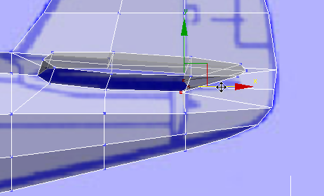
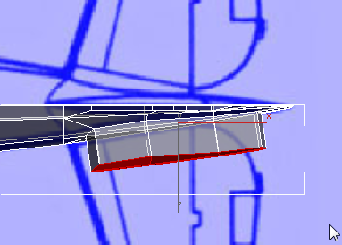
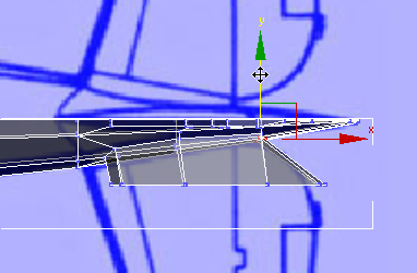
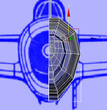
Adjusting the trailing edge of the stabilizer
Front view
Adjusting the trailing edge of the stabilizer
Top view
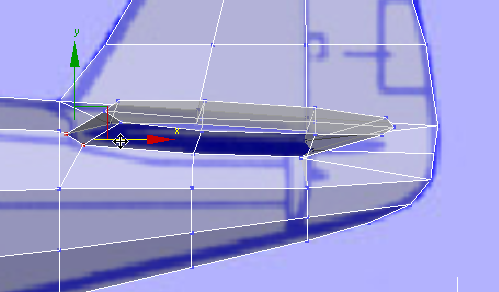
Adjusting the leading edge of the stabilizer
Front view
Adjusting the leading edge of the stabilizer
Top view
(Polygon) again.
 rotate the stabilizer faces
on the Z axis to better follow the direction of the stabilizer.
About 5 degrees is enough.
rotate the stabilizer faces
on the Z axis to better follow the direction of the stabilizer.
About 5 degrees is enough.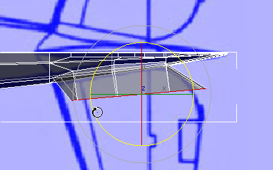
 (Select And Move), then
choose Local as the transform coordinate system (after you rotate
the faces, you can’t rely on View coordinates).
(Select And Move), then
choose Local as the transform coordinate system (after you rotate
the faces, you can’t rely on View coordinates).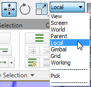
In the Top viewport, move the faces to better match the blueprint image.
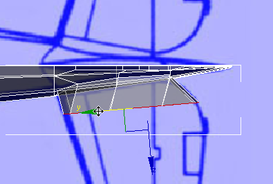
 (Select And Uniform Scale),
choose Local as the coordinate system once more, then scale the
faces up slightly in the Y axis so they match the blueprint image.
(Select And Uniform Scale),
choose Local as the coordinate system once more, then scale the
faces up slightly in the Y axis so they match the blueprint image.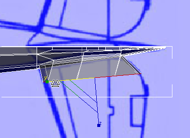
move the faces vertically
in local Y axis to make them horizontal. Watch your work in the
Left and Perspective viewports.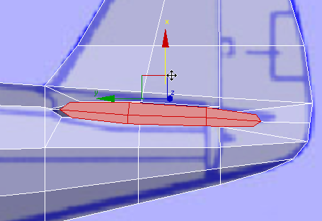
Left view
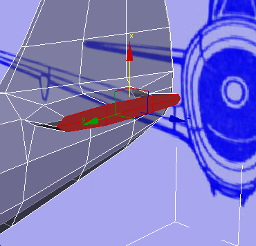
Perspective view
 when the cursor is at a
vertex
when the cursor is at a
vertex
 when the cursor is on an
edge
when the cursor is on an
edge
 when the cursor is on a
face
when the cursor is on a
face