


Begin Modeling the Cockpit
Canopy
To model the cockpit, you begin by shaping the fuselage in the cockpit region, then extruding polygons in that same region. This is the basis for the cockpit canopy, which becomes a separate object.
 open \modeling\p47\p47_03.max,
 select the P-47.
On the ribbon
select the P-47.
On the ribbon  Polygon
Modeling panel, click Modify Mode.
Polygon
Modeling panel, click Modify Mode.
Now that you’ve created the horizontal stabilizers and the wings, the Symmetry modifier has done its work, so you can collapse the airplane model back into a unified object once again.
Convert To Editable
Poly.
Polygon Modeling panel, click  (Vertex).
 move them to match the cockpit
outline in the blueprint image.
move them to match the cockpit
outline in the blueprint image.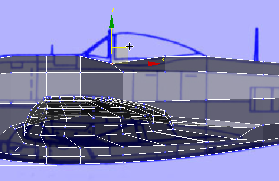
move them forward so the
mesh is a bit more regular.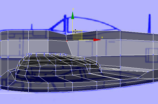
move them to match the blueprint
outline as well.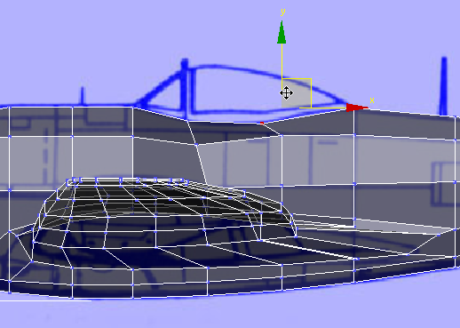
move them forward to adjust
the mesh as you did for the more forward edge.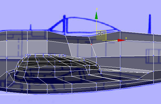
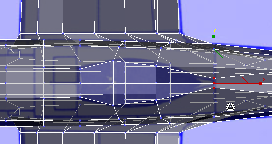
 pan and
  zoom in so you have a good
view of the cockpit area.
zoom in so you have a good
view of the cockpit area.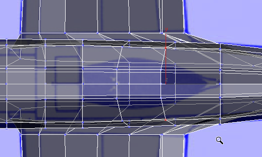
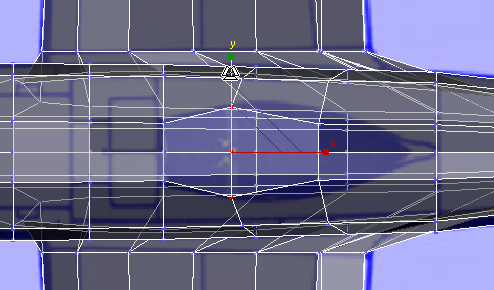
 scale them along the Y axis
so they match the shape of the cockpit (the dark-blue area) in the
blueprint image.
scale them along the Y axis
so they match the shape of the cockpit (the dark-blue area) in the
blueprint image.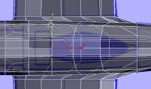
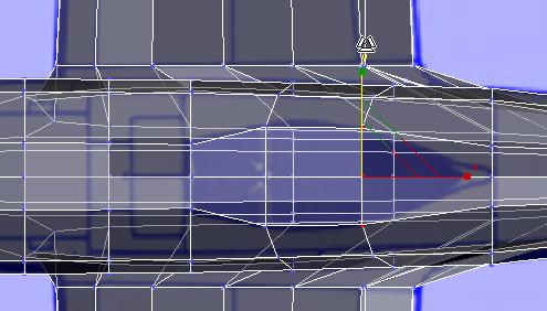
Polygon Modeling panel, click  (Polygon).
 Modify panel Selection rollout, turn
on Ignore Backfacing.
click and Ctrl+click to select the polygons
that make up the cockpit area.
Modify panel Selection rollout, turn
on Ignore Backfacing.
click and Ctrl+click to select the polygons
that make up the cockpit area.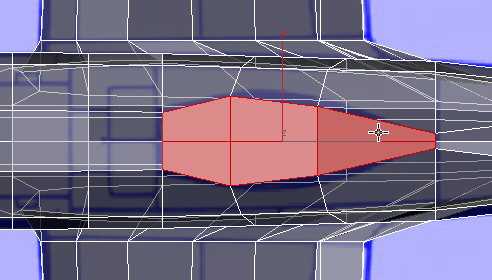
Polygons panel, click  (Extrude). In the Perspective
viewport, extrude the polygons: Watch your work in the Front viewport,
so you can make the extrusion about the height of the cockpit canopy
in the blueprint image.
(Extrude). In the Perspective
viewport, extrude the polygons: Watch your work in the Front viewport,
so you can make the extrusion about the height of the cockpit canopy
in the blueprint image.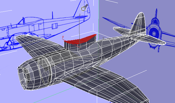
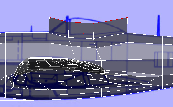
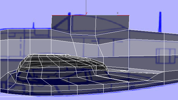
Front view
Align panel, click  (Align Y).
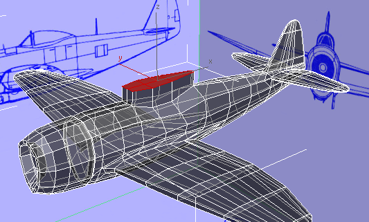
Front view
If you need to, move the polygons so that
in the Front viewport, they are the same height as the canopy in
the blueprint image.
Modify panel Selection rollout, turn
off Ignore Backfacing.