When you select an object and open the texture editor, you see the object's UV coordinates. These are the object's coordinates on the texture. To manipulate them, you must select and move one or more "sample points." Although the term "sample points" (or "samples") is used to describe the points that you select on polygon and NURBS objects, it has a different meaning for each.
When you're working with polygon objects, sample points refer to points at the corners of each polygon. When you select a single polygon with tearing mode on, only the sample points at each of its corners are selected. This allows you to detach individual polygons from the rest of the UV samples in the texture editor and move them to arbitrary locations on the texture without affecting adjacent polygons' positions on the texture.
If tearing mode is off, the sample points of adjacent polygons are added to the selection, keeping the polygon "glued" to the rest of the UV coordinates.
Sample points on NURBS do not correspond to vertices because points on NURBS do not lie on the surface. Instead, they correspond to a regular sampling of the surface.
Using vertex selection on a NURBS object selects individual points, while using polygon selection selects groups of points that, though not technically polygons, form a closed polygon if joined together. Similarly, selecting edges on a NURBS object selects the points joined by the edge. On a single surface mesh, however, you cannot detach a selection of points from the entire set of UV coordinates.
Polynode bisectors are short lines that bisect each polynode on a polygon object. There is one polynode for each polygon attached to a point. When polynode bisectors are displayed in the texture editor, and the Vertex or All selection filters are active, you can use them to select the individual UV coordinates stored at each polynode. This is the most granular way of selecting UV coordinates.
Polynode bisectors are displayed in different ways, depending on the selection filter. For more information about the various selection filters, see Basic Selection Filters.
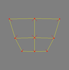
Both the Vertex selection filter and the All selection filter allow you to select individual UV coordinates. As such, activating either filter displays all of the object's polynode bisectors.
Selected bisectors are displayed in red, while unselected bisectors are displayed in a light purple.
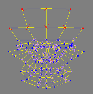
The Edge selection filter and the Polygon selection filter only allow you to select the coordinates belonging to selected edges or polygons respectively. As such, polynode bisectors are not displayed until you make a selection. Then, only the selection's bisectors are displayed.
Since the displayed bisectors are always selected, they are always displayed in red.
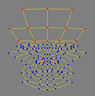
The Island selection filter and the Cluster selection filter, which can be used in conjunction with the other selection filters, display polynode bisectors in accordance with whatever other filter is active.
Polynode bisectors are displayed by default, but you can toggle their display on and off. This is useful when you're working with very complex meshes, in which case the bisectors tend to overlap and obscure the texture image.
You can control the appearance of polynode bisectors by setting a few preferences.
From the main menu, choose File  Preferences to open the preferences window.
Select Display in the explorer pane to open the Display property editor in the right pane.
On the Component Display tab, set the following Polynodes preferences as needed:
Min Length in Pixels of Polynode Bisectors sets the minimum length of polynode bisectors in pixels.
Max Length in Pixels of Polynode Bisectors sets the maximum length of polynode bisectors in pixels.
Scale Factor w/r to Smallest Adjacent Edge sets the length of the polynode bisector as a fraction of the shorter of the two adjacent edges.
For example, if this option is set to 0.2 and the shorter edge is 50 pixels long, then the bisector will be 10 pixels long as long as the minimum and maximum lengths are respected.
Pitch Angle in Degrees of Polynode Bisectors sets the angle in degrees by which the bisector sticks out from the plane of its two edges.
In 3D view, this makes it easier to select a bisector when the polygon is almost perpendicular to the screen.
In the texture editor, adjusting this value has the effect of shortening or lengthening the bisectors since there is no representation of depth.
The Texture Editor provides selection filters so you can easily select a vertex, an edge, a polygon, a cluster, or all of these components. To select UV coordinates from the texture editor work area, activate one of the following selection filters and select points, polygons, edges, clusters, or individual UV coordinates.
Selections made with any filter can be extended using the bleeding options, which are described in Using Tearing and Bleeding to Extend Selections.

Vertex selection is the most granular of selection filters. You can select a single point or a collection of several points. With the Rectanle Selection tool, clicking and dragging across a point selects all corresponding samples but single-clicking raycast-selects a single sample. You can also select individual UV coordinates by displaying polynode bisectors.

Edge selection is similar to the Vertex filter except that the Edge selection tool adds adjacent points to your selection.

Polygon selection selects the UV coordinates of every polygon connected to a selected point, or the UV coordinates of selected polygons (you can click inside a polygon to select it).

All selection selects any type of component. At each selection click, it searches for edges, vertices, and polygons consecutively. This is a good selection filter to use with the Move Component tool (see Using the Move Component Tool).
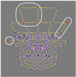
In this example, going clockwise from left, a vertex, a polygon, and an edge were clicked. The resulting selections are circled in white.

Island Selection is used in conjunction with any other selection filter. It selects all of the UVs connected to a selected UV coordinate (bisector), point, polygon, or edge.
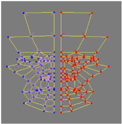
In this example, island selection is used with vertex selection. When a point on one half of the face is selected, every connected point is also selected, but the other half is not selected.

Cluster selection is used in conjunction with any other selection filter, allowing you to select sample point clusters created in the texture editor.
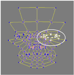
In this example, the points around the eye area were turned into a cluster and selected using the Vertex and Cluster selection filters. The resulting selection is circled in white.
The tearing and bleeding modes affect what gets selected and manipulated when you click on components in the texture editor.

When tearing is off, connected and coincident UV samples are automatically affected by any manipulation even if they are not explicitly selected.
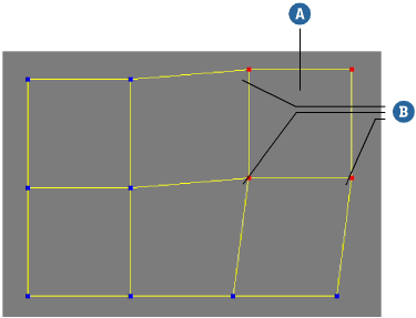
Polygon (A) was selected and moved. The samples (B) were also affected.
When tearing is on, it's possible to separate samples into discontinuous islands.
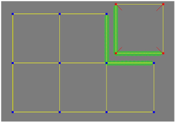
 Bleed Selection after selecting samples and before manipulating them.

When polygon bleeding is on and you select samples, all samples belonging to the adjacent polygons become selected automatically. This allows you to move the polygons in a block without internal distortion.
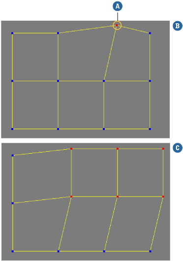
The effect of moving a selected vertex (A) with polygon bleeding off (B) and on (C). In both cases, tearing is off.
Though selecting points, polygons, and clusters from the Texture Editor's work area is fairly straightforward with simple objects, it can get quite complicated with more complex objects because there is no representation of depth. In some cases, you may find it simpler to make your selections from a 3D view.
The relationship between the 3D views and the texture editor is bi-directional, meaning that component selections in the 3D views are reflected in the texture editor and vice-versa. However, because selections in the texture editor are always groups of UV coordinates, there's usually some translation between views.
In 3D views, you can select components using most selection filters (polygon, cluster, samples, and so on) and the corresponding UV coordinates will be selected in the texture editor (provided that the Auto-Sync Selection preference is on — see Auto Syncing 3D View Selections).
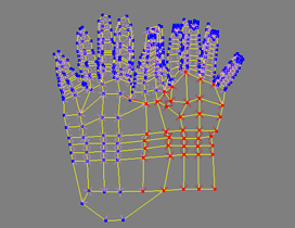
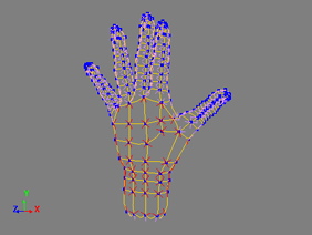
When you select UV coordinates in the texture editor, the selection filter in the 3D views is automatically set to Samples, and the corresponding sample points are selected.
|
|
| Selecting these UV coordinates in the texture editor... |
... selects the corresponding sample point in the 3D views. |
Vertex selection information is not transferred to the texture editor for NURBS objects because there is no defined correlation between vertices on a NURBS object and sample points.
Only Knots, U/V Knot curves, sample points, boundaries and subsurfaces are transferred to the texture editor, when selected in a 3D view.
The Auto-Sync preference controls whether the corresponding UV coordinates are selected in the texture editor when you select components in 3D views, and vice versa.
From the texture editor menu, choose Select  Auto-Sync Selection.
From the texture editor menu, choose File  Preferences to open the Texture Editor Preferences property editor. From the General tab, toggle the Auto-Sync option.
The Sync Method preference controls the type of component selected in the 3D views when samples are selected in the texture editor:
When you select UV coordinates from 3D views, you can automatically isolate the selection in the texture editor by activating the Auto Show Selected option.

You can lock the selection in the texture editor by clicking the Lock button in the command bar. Locking the texture editor keeps the current object, texture and selection displayed, regardless of whether you change the selection in a 3D view.
If you are working in lock mode, you can still update the texture editor with selections made in a 3D view and vice-versa.
You can set a preference to control what happens in the texture editor when you select a polygon cluster in a 3D view.
By default, the appearance of the texture on the selected object is updated interactively in the 3D views whenever you modify sample points in the texture editor. If necessary, you can turn this behavior off so that the texture in the 3D view updates when you release the mouse button after any modification.
Projection selection filters make it easy to select the sample points on the right, left, top, bottom, front, or back regions of an object. The region is determined based on the object's position in 3D space. If part of a projection is hidden, the selection is determined using only the currently visible points.
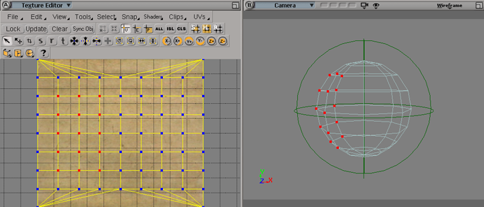
The example above shows a sphere mapped onto a cardboard texture. The selected points are the result of a left (X-) projection selection. You can see the corresponding points on the sphere in the 3D view.
If you want to adjust the scope of a projection selection, you can set a threshold angle value in the Texture Editor Preference property editor. A sample point is included in the projection selection when the angle between its surface normal and the object's axis, as defined by the projection selection, is less than the threshold value.
When working with a complex object and selecting a small cluster or just a few points, you can hide the unselected portion of your object with a single click.
Once you have selected the point, cluster, or polygon(s) you wish to edit, click the Show Selected icon on the texture editor command bar. All unselected points will be hidden, thereby uncluttering the work area.

Click the Show All icon to unhide all points.
If you wish to hide specific points, you can select them and click the Hide Selected icon.
 Except where otherwise noted, this work is licensed under a Creative Commons Attribution-NonCommercial-ShareAlike 3.0 Unported License