You can project curves onto surfaces and then use the result to remove a portion of the surface, or for any other modeling purpose. This is useful for modeling manufactured objects like car parts with holes or for creating smooth surfaces that aren't four-sided like a standard NURBS patch.
Both surface and trim curves involve projecting a curve object onto a NURBS surface. The difference is whether the result is used to remove a portion of the surface or not.
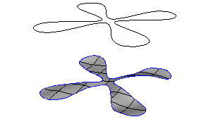
If the curve object is just projected and nothing more, the result is called a surface curve. It is a new component of the surface. This surface curve can be used like any other curve component of the surface (isoline, knot curve, and so on) for modeling operations like Loft, Extend to Curve, and others.
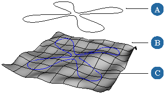
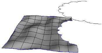
The curve object (A), the NURBS surface (B), and the resulting surface curve (C).
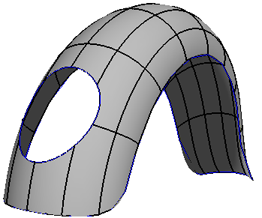
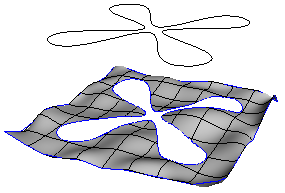
If you use the projection to remove part of the surface, it is called a trim curve. Trims are useful for making holes in surfaces and for making NURBS patches that don't have the usual four-sided boundary.
|
|
Trimming affects the visible portion of the surface. All the underlying points are still there and you can still affect the surface's shape by moving points in the trimmed area. However, you can still use trimmed surfaces as collision objects for soft body and cloth simulations, and the simulation uses the exact shape of the trimmed surface.
By default, surface and trim curves are displayed in dark blue when you select the surface or when it is active for component selection. On trimmed surfaces, the U and V boundaries are also displayed in dark blue, but you can ignore that — they are not truly considered trims.
You can control the resolution used to draw trim and surface curves. The Hardware Display tab of Geometry Approximation property editor controls the resolution used in the OpenGL views, while the Surface Trim tab controls the resolution used for rendering. For more information, see Geometry Approximation Property Editor [Properties Reference].
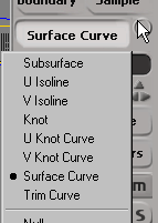
When working with trim and surface curves, you can use the Trim Curve and Surface Curve component selection filters that are available on the Select panel when you select a surface object. For more information about selecting components in general, see Selecting [Scene Elements],
Surface and trim curves can be extracted in exactly the same way as other components of surfaces (like isolines and knot curves). See Extracting Curves from Surfaces.
In Softimage, curve objects are mapped onto surfaces using a parallel projection. The projection follows the normal of the average plane of the curve and extends infinitely both directions.
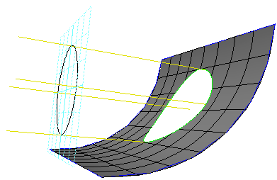
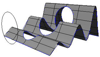
The curve is projected onto both the front and back sides of a surface and can intersect the surface multiple times if the surface is folded. The curve can punch a hole through the surface or just take a bite out of the edge.
Here are some things to keep in mind when creating curves to use for projecting:
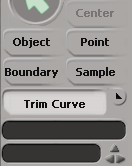
The Modify  Surface Trim by Projection command is used both to project a curve onto a surface and to trim a surface by a curve.
Choose Modify Surface Trim by Projection from the Model toolbar. A picking session starts.
Pick a curve object. The curves are projected onto the surface and, by default, the surface is trimmed using all projected curves.
In the Trim Surface by Space Curve property editor, do any of the following:
To trim the surface using only some of the projected curves, click Pick Trims and then pick the desired surface curves. Right-click when you have finished picking.
To trim the surface using all the projected curves, click Trim with All. This is useful if you used Pick Trims or Project All and then changed your mind.
To project the curve onto the surface, click Project All. The surface curves become components of the surface and can be used in modeling operations like loft and others.
Adjust any of the other options as needed:
When trimming rather than simply projecting, use Is Boundary to determine which portion of the surface to keep: make a hole by keeping the area outside the curve (off) or crop the outside leaving only the interior (on).
Use Projection Precision to control the precision used to calculate the projection. If the shape of the projected curve is not accurate, increase this value.
However, high values take longer to calculate and may slow down your computer. For best performance, set this parameter to the lowest value that gives good results.
Deleting a trim allows you to remove a trim operation even after you have frozen the surface's operator stack. If you have not frozen the stack, you can alternatively reopen the Trim Surface by Space Curve property editor and use Pick Trims, or delete the Trim Surface by Space Curve operator altogether.
Here are some notes about trimming and projecting:
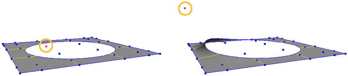
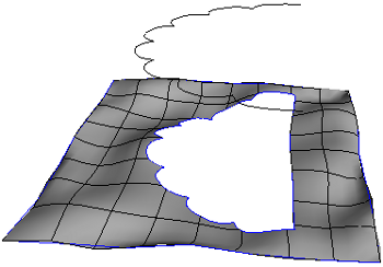
You can trim with open curves. This can be useful if you are just taking a bite out of an edge of a surface; you don't need to close the curve first. However if the entire curve can be projected onto the surface, a straight segment connects the end points.
|
|
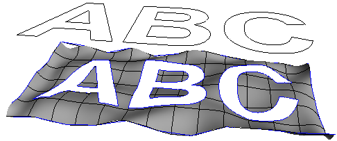
You can use a single curve object composed of multiple subcurves, such as a curve created with text or by importing an EPS file. In such cases, each subcurve creates a separate surface curve or trim curve component.
When trimming, disjointed subcurves (such as the exterior curves of different characters) produce separate holes, while interior subcurves produce "islands" within the holes (or vice versa, if Is Boundary is on).
You can use a second trim operation to create an island in the trimmed area. For the second trim operation, make sure that Is Boundary is on.
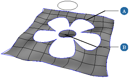
The first trim makes a hole (A) and the second trim makes an island (B).
When projecting curves onto assembled surface meshes, multiple trim or surface curves will be created if the projection intersects a boundary between subsurfaces.
You can animate the surface and curve objects to change the resulting trim or surface curve over time.
 Except where otherwise noted, this work is licensed under a Creative Commons Attribution-NonCommercial-ShareAlike 3.0 Unported License