Surface meshes are quilts of surfaces joined at their boundaries, just as polygon meshes are quilts of polygons joined at their edges. They are a special type of renderable geometry. Surface meshes are ideal for complex envelopes on skeletons.
The component surfaces of a surface are called subsurfaces. The continuity at their seams is maintained automatically no matter how the surface mesh is deformed. Subsurfaces can also have their own local clusters, materials, and textures.

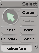
The main distinction between surface meshes and ordinary surfaces (such as a primitive or a surface you create) is the number of subsurfaces. Ordinary surfaces have just one subsurface — they can be thought of as extremely simple surface meshes. You can select subsurfaces with the Subsurface filter in the Select panel.
Junctions are the boundaries where subsurfaces meet. For smooth continuity to be maintained across a junction, the control points of the subsurface boundaries must line up. Indeed, much of the art of modeling with surface meshes lies in constructing subsurfaces so that their boundary points line up properly. For some information about different types of junctions, see Junction Types.
The surface continuity manager (SCM) is the operator that ensures that surface meshes are smooth across their junctions. In explorer views, it is called SCM Fixer Op2 and always remains at the top of the operator stack. Only one surface continuity manager can manage the continuity of a surface mesh at any time.
SCM is applied automatically when you assemble a surface mesh. However, if you freeze the operator stack, you will need to reapply it manually. For more information, see Applying SCM Manually.
Sometimes you want continuity across some junctions but not others, or you want to create a hole in a junction by joining only some of the points. There are two ways to exclude points from surface continuity management:
If at least one pair of corresponding points across a junction are farther apart than a specified tolerance, the entire boundary is excluded from continuity management.
You have the option of excluding specific points from continuity management. The other points on the same junction are not affected. This lets you create holes for mouths, eyes, and so on. For more information, see Excluding Points from Continuity Management for the complete procedure.
 Except where otherwise noted, this work is licensed under a Creative Commons Attribution-NonCommercial-ShareAlike 3.0 Unported License