There are several considerations when modeling the surfaces that will be assembled into a surface mesh:
All surfaces must be either cubic NURBS in both the U and V directions, or linear NURBS in both U and V.
The SCM (Surface Continuity Manager) does not work with quadratic NURBS.
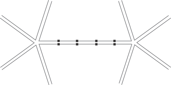
Surface meshes work by locking boundary points together then managing the continuity across the junction. Each boundary point can match a single point on another surface's boundary. You can insert and remove knots to create the necessary boundary points. For more information, see Adding Knot Curves and Removing Knot Curves.
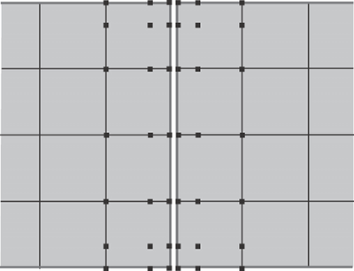
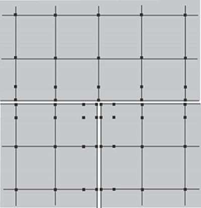
SCM uses the next row of points after the boundary to calculate continuity. Make sure that there are enough rows between two junctions: preferably two or more.
The assemble operation uses distance to determine whether two points across a junction should be locked together, so make sure points are overlapping or very close together. You can apply the Snap Boundary operator to help line up points along boundaries.
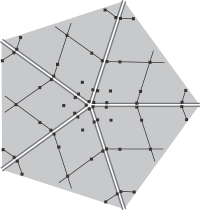
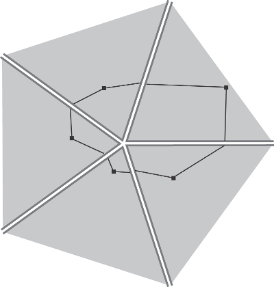
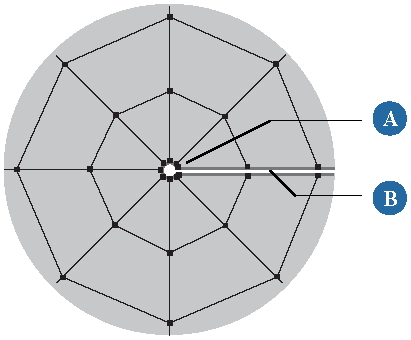
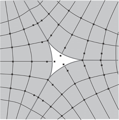
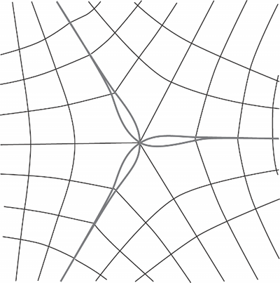
Surfaces can meet at an edge (I Junction), a T junction, or a star junction. Alternatively, an edge of one or more surfaces may be collapsed to a single point as at the poles of a sphere.
In an I junction, two surfaces join along a common border. This is the simplest of all possible junctions.
A T junction joins three surfaces. The border of one surface is joined to the borders of the other two. In addition, the other two surfaces share a border.
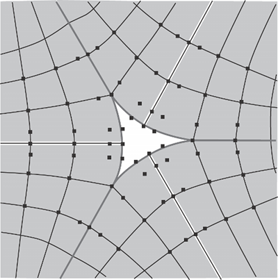
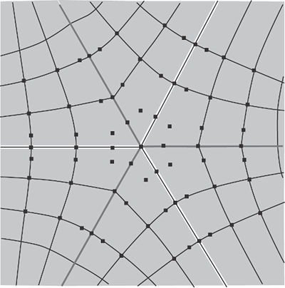
You can use multiknots to create discontinuities that help to line up surfaces. This is especially useful to eliminate holes where three or more surfaces meet in a complex way.
Individual subsurfaces can have local materials and textures. However, UV texture projections are not supported.
If you have already applied materials and textures to the individual surfaces, you have the option of copying them locally when you assemble. Be aware however, that the texture projections remain attached to the original surfaces — thus if you move the assembled surface mesh without moving the projection, the texture will slide.
Freeze the assembled surface mesh. This also freezes the texture projections on it. However, you will need to manually reapply the surface continuity manager as described in Applying SCM Manually.
Constrain or parent the original texture projections to the assembled surface mesh.
 Except where otherwise noted, this work is licensed under a Creative Commons Attribution-NonCommercial-ShareAlike 3.0 Unported License