Knifing and slicing allow you to split the polygons of a mesh object along any plane. Both techniques add a Slice Polygons Op node to the construction history, but the workflow is different:
Modify  Poly. Mesh Slice Polygons applies the operator and open Modify Poly. Mesh Slice Polygonss its property editor so that you can modify values. This command is useful if you need to specify many settings: plane, offset,
number of slices, spacing, and so on. See Slicing Polygons.
Poly. Mesh Slice Polygons applies the operator and open Modify Poly. Mesh Slice Polygonss its property editor so that you can modify values. This command is useful if you need to specify many settings: plane, offset,
number of slices, spacing, and so on. See Slicing Polygons.
Modify Poly. Mesh Knife Tool is an interactive tool that lets you slice polygons perpendicularly to the viewing plane by drawing a line in a 3D view.
The operator is applied but its property editor does not open automatically. This tool is useful when you want to quickly
and simply cut polygons along a custom plane. See Knifing Polygons.
If you want to subdivide polygons along multiple orthogonal planes, you can dice them instead. See Dicing Polygons.
Choose Modify Poly. Mesh Knife Tool from the Model toolbar, or press [.
Click in a 3D view to define one endpoint of a line, and then click in a second location to define the other endpoint.
|
|
|
If desired, press Shift to snap at multiples of the Rotate increment (specified in the Transform preferences).
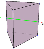
The polygons are split along an infinite plane that contains the line and is perpendicular to the viewing plane.
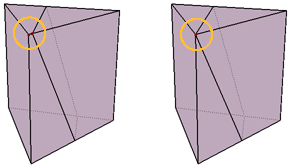
Before you start another cut or exit the Knife tool, you can adjust the cutting plane if desired:
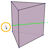
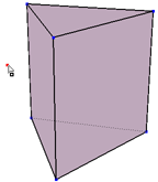
Move the mouse pointer over either one of the two endpoints you drew. When the mouse pointer changes from Knife (an arrow) to Move Point (an arrowhead and box as shown above) and the point is highlighted red, you can click and drag the point to a new location. This lets you adjust the angle of the slice. You can do this only in the same view you drew the endpoints, and only if the cutting plane is still perpendicular to the viewing plane (for example, if you have not orbited in supra mode). If desired, press Shift to snap at multiples of the Rotate increment (specified in the Transform preferences).
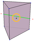
Move the pointer over any of the newly created edges (highlighted in green). When the mouse pointer changes from Knife to Move Point and the both points are highlighted red, you can click and drag the edges to a new location. This lets you adjust the position of the slice. You can do this in any 3D view.
Clicking anywhere else will start a new cut.
You can also display a context menu by pressing and holding the right mouse button (right-clicking quickly terminates the Knife tool). The context menu contains the following items:
Create Grid and Connect creates an implicit grid that you can transform to manipulate the cutting plane. See Specifying the Cutting Plane.
Inspect Operator displays the property editor for the Slice Polygons operator. See Slicing Options.
The Knife tool remains active, so you can repeat steps 3 and 4 to make more cuts if desired.
To exit the Knife tool, right-click or press Esc. Alternatively, simply activate another tool.
To make adjustments to the operation after you have exited the Knife tool, open the Slice Polygons Op property editor in the object's modeling stack. For more details, see Slicing Options.
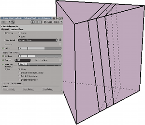
The Slice Polygons Op property editor allows you to control various options, such as the position of the cutting plane and the number of slices.
The Slice Polygons Op property editor opens automatically when you apply the operator manually using Modify Poly. Mesh Slice Polygons from the Model toolbar.
If you are slicing interactively and the Knife tool is still active, you can open the property editor for the most recent operation by pressing and holding the right mouse button, then choosing Inspect Operator from the context menu.
Of course as with any modeling operator, you can always redisplay the property editor later by clicking on its icon in an explorer. See Viewing and Modifying Operators.
The cutting plane determines the location and angle of the slice. You can:
Use the XY, YZ, or XZ plane of the object's local or global reference frame.
Specify a custom plane by entering position and rotation values numerically.
Specify a custom plane interactively by connecting the operator to a 3D object and then translating and rotating it.
On the General tab of the Slice Polygons Op property editor, set Plane Normal to Custom Plane.
On the Custom Plane tab, set the Position and Rotation values of the custom plane you want to use.
The values entered here are interpreted as either local or global coordinates, depending on the value of Reference set on the General tab.
Connect the cutting plane to an object by doing one of the following:
To use an existing object in the scene to define a custom plane, right-click on the connection icon next to the Plane Normal on the General tab of the Slice Polygons Op property editor.
Choose Pick and Connect, then click on the desired object in any view. The cutting plane immediately aligns with the center of the object you picked.
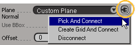
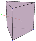
To create a new implicit grid and use it to define a custom plane, press Create Grid and Connect (near the bottom of the General tab). An implicit grid is created at the position of the current cutting plane.
Alternatively, you can invoke this command by right-clicking on the connection icon and choosing Create Grid and Connect. If the Knife tool is active, you can also press and hold the right mouse button, then choose this command from the context menu.
The connection icon turns red to show that an object is connected.
Translate and rotate the object into the desired position. As you move the object, the cutting plane updates automatically. The Position and Rotation values on the Custom Plane tab of the Slice Polygons Op property editor show the current position of the object, but cannot be modified directly.
When you are done, you can disconnect the object (if desired) by right-clicking on the connection icon and choosing Disconnect. The cutting plane is no longer affected by the transformation of the object.
Alternatively, if you no longer need the object in your scene, you can simply delete it and it is disconnected automatically.
You can also leave the object connected, for example, if you want to animate the position and angle of the slice by animating the transformations of the object. In
If you leave the object connected, you can activate Update With Transfo. When this option is on, the slice is updated every time the sliced object is moved (not just when the slicing object is moved). This allows you to make the slicing object a child of the sliced object and transform the whole hierarchy without affecting the position of the slice. However, it is best to leave this option off unless necessary because it forces the slice to be recalculated every time the object is transformed.
You can offset the slice along the normal direction of the cutting plane. This can be useful, for example, if you want to animate the position but not the angle of the slice.
You can also force the slice to pass through a point's position by offsetting it the required amount. This is useful if you missed slicing through a desired vertex when using the interactive Knife tool.
Adjust the Offset slider on the General tab of the Slice Polygons Op property editor. The slice slides along the normal of the cutting plane.
The units for the offset value depend on whether Use BBox is on or off. If it is off, values are in Softimage units. If it is on, the slider's name changes to Offset % and values are percentages of the object's bounding box. The bounding box is calculated with respect to the local or global frame, depending on the value of Reference. If you are using custom planes, Use BBox is not available and the offset value is always in Softimage units.
Click Snap Offset to Point on the General tab of the Slice Polygons Op property editor. A picking session begins.
Note that Snap Offset to Point has no effect if Distribute Slices is on.
Pick the desired vertex in a 3D view. The vertex does not need to be on the same object as the slice — simply click on the desired object and then click on the desired point.
The correct Offset value is automatically calculated and the slice passes through the picked point.
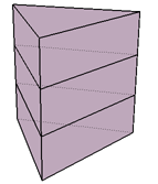
To create multiple parallel slices, set Nb Slices on the General tab of the Slice Polygons Op property editor to the number of slices you want.
There are two ways to control the spacing between the slices:
To use a specific distance between adjacent slices, set Spacing to the desired value. If Use BBox is off, values are in Softimage units. If it is on, values represent percentages of the extent of the object's bounding box in the appropriate axis.
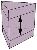
To distribute the slices evenly along the extent of the object's bounding box in the direction of the cutting plane's normal, turn Distribute Slices on.
Note that this option is available only when Use BBox is on, so you cannot use it with custom planes. In addition, the bounding box is calculated with respect to the local or global frame, depending on the value of Reference.
Slicing sometimes creates very small edges and polygons when a slice passes close to an existing vertex. You can eliminate these small components using Point Snap Tolerance on the General tab of the Slice Polygons Op property editor — if a new point created by the slice operator is closer to an existing point than the tolerance value, the new point will get snapped to the existing point and welded. As a result, some of the new edges are no longer exactly parallel to the cutting plane, but no existing points get moved.
On the General tab of the Slice Polygons Op property editor, Action specifies the components created or removed by the slice operation:
Disconnect Edge Loop(s) breaks the object apart into separate, disconnected islands of polygons along the new edges by creating pairs of opposing
boundary edges instead of simple edges. This results in disconnected islands of polygons. The effect is the same as if you
selected all new edges created by the splice operation and then chose Modify Poly. Mesh Disconnect Edges.
Delete Polys Above deletes the polygons in the direction of the cutting plane's normal from the slice's position (or the last slice's position, in the case of multiple slices).
Delete Polys Below deletes the polygons in the inverse direction of the cutting plane's normal from the slice position (or the first slice's position, in the case of multiple slices).
The three buttons in the Select box on the General tab of the Slice Polygons Op property editor are convenient for quickly selecting specific components:
Edge Loop(s) selects all edges created by the slice operator.
Polys Above selects the polygons in the direction of the cutting plane's normal from the slice position (or the last slice's position, in the case of multiple slices).
Polys Below selects the polygons in the inverse direction of the cutting plane's normal from the slice position (or the first slice's position, in the case of multiple slices).
 Except where otherwise noted, this work is licensed under a Creative Commons Attribution-NonCommercial-ShareAlike 3.0 Unported License