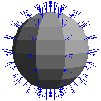
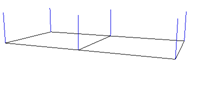
Shading normals are vectors that are perpendicular to the surface of polygons at each corner.
Normals on a polygon mesh sphere as indicated by blue lines.
In Softimage, polygon meshes can have auto normals or user normals:
Auto normals are calculated automatically based on a mesh's geometry. See Controlling Automatic Normals on Polygon Meshes.
User normals are custom-defined. See Setting User Normals on Polygon Meshes.
The rest of this section describes normals in general.
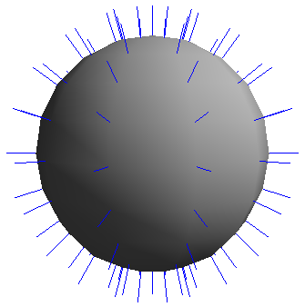
The direction of normals indicates the "front" surface of an object. On a closed object such as a sphere, normals should be on the outside (assuming that the camera is also on the outside). On an open object such as a grid, they should be on the side facing the camera.
When you draw a polygon manually, the direction of the auto normals is determined by the direction in which you draw the vertices.
If the vertices are drawn in a counterclockwise direction, the normals face toward the view's viewpoint.
If the vertices are drawn in a clockwise direction, they face away from the view's viewpoint.
When normals point away from the camera, polygons do not shade properly. When normals point away from you in a geometry view, you cannot select them using the raycast selection tools unless you activate Include Backfacing Polygons in your Tools > Selection preferences (see Selection Preferences).
Normals control the shading of an object. They indicate the orientation of the object's surface, which affects how much illumination reaches the camera from different areas. This results in a difference of shading between the light and dark areas across the surface.
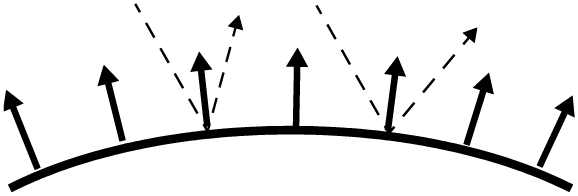
In the real world, normals are perpendicular to an object's surface at every location. The angle at which light bounces off a surface depends on the normal at that location.
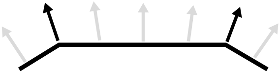
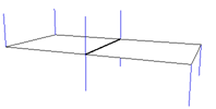
In the 3D world, smooth surfaces are approximated by flat polygons. The normals are stored at the corners of polygons (black) and interpolated for other locations (gray) across the surface of a polygon mesh.This produces a shading similar to that of a smooth, curved surface.
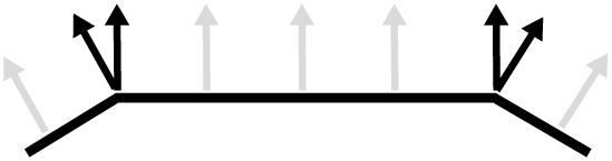
When the normals at the polygon corners are not averaged together, there is a discontinuity that causes a faceted appearance with "hard" instead of smooth edges.
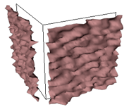
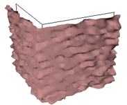
Discontinuity in the shading normals between polygons also affects displacement at render time. If there is a discontinuity across an edge, the displacement occurs in different directions on either side of the edge — the result is "exploded" polygons!
If the normals of two adjacent polygons point in opposite directions, then a double edge is drawn between the polygons to preserve the integrity of the mesh. The double edges are considered boundaries and are displayed in light blue if Boundaries and Hard Edges are visible in a 3D view.
|
|
| When normals point in the same direction, the adjacent polygons share a single edge. |
When normals point in opposite directions, a double edge is drawn between the polygons. |
If this happens accidentally, you can fix it by inverting selected polygons as described in Inverting Auto Normals.
 Except where otherwise noted, this work is licensed under a Creative Commons Attribution-NonCommercial-ShareAlike 3.0 Unported License