Density | Color | Shading | Marching | Lookup Table | Preview | Framebuffer | Final Gathering | Shadows | Render Tree Usage | Basic Workflow for Using the Particle Volume Cloud Shader
The Particle Volume Cloud shader is a volume shader that renders a point cloud's bounding box as a volume. This shader lets you create particle volumes with a low density like clouds, dust, smoke, and fog.
Because rendering volumes and raytraced shadows can be time-consuming, this shader uses a lookup table to store the shadows and other volume data of adjacent voxels (voxels are points/areas in 3D space).
You can use the Particle Renderer or Particle Shaper shader compounds to get going quickly with particle volumes. They both contain variations of the Particle Volume Cloud shader, the Particle Density shader, plus some other shaders to help you set up for basic volume effects. As well, fewer parameters of these shaders are exposed so they're simpler to use.
See Particle Renderer Compound for information.
Here are some general tips to help you set up the lighting for particle volume effects:
A rule of thumb with all rendering: always set the lighting first to create the correct look for the particles, then set the color.
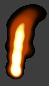
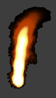
Put light into the center of the base of particle cloud volume to create a glowing, light-scattered effect.
If you're creating smoke and you want it lit at the edges (rim lighting), use two or more back lights.
On the Shading tab, you can select specific lights in your scene to use for rendering. By default, all lights in the scene are used.
If you're using light Scatter option on the Color tab, set the Light Attenuation values for your light (such as a point light) to determine how the light's intensity falls off over distance, which affects the light scattering.
| Global Density |
The density of each particle volume. This sets the overall effect of the density on the particle, with the center of the particle being more opaque than its edges. Low density values give softer, smoother effects (more transparency) while higher density values create more well-defined details and edges (more opacity). |
| Per Ray Type |
Fine-tunes the density of the volume depending on the ray type:
|
For tips on setting up the color values, see Particle Volume Cloud.
Ambient occlusion simulates indirect illumination which gives good detail in the shadows, as well as fractal noise patterns such as those created by the Fractal Scalar shader.
Ambient occlusion works by firing sample rays into a predefined hemispherical region above a given point on an object's surface in order to determine the extent to which the point is blocked (occluded) by other geometry.
Once the amount of occlusion has been determined, a bright and a dark color are returned for points that are unoccluded and occluded, respectively. Where the object is partially occluded, the bright and dark colors are mixed in accordance with the amount of occlusion.
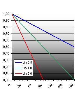
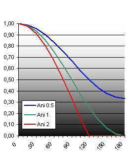
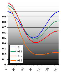
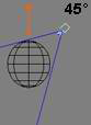
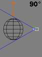
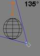
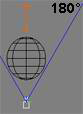
The following graphs show the brightness of the object depending on the angle light-camera (light-normal, respectively). For each shading model, different strength values have been used.
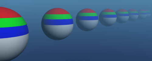
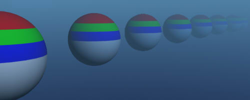
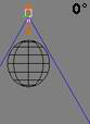
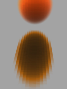
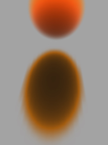
The following images show renderings of a volume sphere from different camera directions.
Note that shading without normal shading looks constant in this example, but don't forget the shadows! They will do their part for the shading and darken volume areas farther away from the light.
The marching defines how often the volume is sampled along the camera ray.
The lookup table is a very low-resolution version of the particle volume. It stores color and shadow information for a fast lookup. The shader computes all shadows for this low-res volume and applies it to the final volume. The final lookup table you create should cover the average shape of the particle volume, but does not require detail, which is provided by the input texture shaders.
For information on how to set up the lookup table, see Setting the Lookup Table.
Generally, the shader uses voxels to create volume per particle. You can define the voxel size by setting the cell size in the lookup table. Smaller cell sizes create a better look and nice shadows, but more time and memory is required; larger cell size is faster and takes less memory, but gives little interpolation, so the look is not as good or detailed. As with anything in rendering, this is the eternal struggle: time and memory versus detail and good looks!
The more detail you have in your volume, the more cells you need for your shadows, otherwise you could get flickering shadows. If you have lots of detail in your volume, but you want to use big cells for smooth shadows, increasing the number of input samples per cell can give you better results.
You can define the voxel size by setting the cell size in the lookup table. You should aim to set this size to something that is appropriate to the size of the particles.
For example, if the particle size is 0.5 units, you should not set the Cell Size to something much higher if the particles are separated in space. Large cell sizes can sometimes lead to non-rendered blocks, if a detail (a single particle in space) is missed by the lookup table.
But don't set it too small either! If you have a particle size of 10, don't set the cell size to 0.5. Small cell sizes lead to long render times, which you want to avoid when you are testing out values.
| Max Memory to Prevent Crash |
While you are tuning the shader, you will probably reach the memory limit. This parameter catches this case and prevents mental ray from stopping the rendering. It causes the volume to be rendered with lower settings and in a red color to warn you that you are reaching the memory limit. For tips about reducing the memory used, see Memory Limit. |
You can preview the effects of this shader using only the options on this page. This is useful for isolating and optimizing different options for troubleshooting. For the final rendering, however, the "real" settings on the other property pages are used.
Select each option that you want to render: Illumination, Shading, Specular, Ambient Occlusion, and Scatter.
If that option is not selected, the shader does not render that feature.
For tips on setting the Slices parameters, see Particle Volume Cloud.
You can render some color channels of this shader into framebuffers. Framebuffers are used to store rendered pixel data, then the buffer content is output to image files which can be used in compositing programs. For more information about framebuffers in general, see Render Channels & Framebuffers.
If you select Not in Main Buffer for any of these options, that channel is rendered only in the frame buffer, but not in the main image.
| Ambient |
See Color. |
| Illumination |
See Illumination. |
| Specular |
See Illumination. |
| Scattering |
See Illumination |
| Final Gathering |
See Final Gathering. |
| Distance |
The minimum and maximum distance from the camera. |
| Motion |
Maximum motion in screen pixels. Use this framebuffer to output motion vector data that can be used for motion blur in a compositing program. |
| Ambient Occlusion |
See Ambient Occlusion. |
| Ambient2 |
This is a second Ambient input, in case you want to render a second color. You can set the color of it here. |
| Normal |
If you use Normal Shading, you can render the normal into a frame buffer for post-lighting. See Normal Shading. |
Final gathering is a way of calculating indirect illumination without using photon energy. Instead of using rays cast from a light to calculate illumination, final gathering uses rays cast from each illuminated point on an object's surface. The rays are used to sample a hemispherical area above each point and calculate direct and indirect illumination based on what the rays hit.
Sets the marching step size for final gather rays.
The Particle Volume Cloud shader is the base shader for creating particle volume effects, but you need to use the Particle Density shader with it to give each particle a shape within the volume.
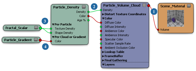
Open the Particle Volume Cloud shader's property editor and follow these guidelines for getting set up:
You first need a Density Input (see Density). Plug the Particle Density shader into the Density port of the Particle Volume Cloud shader.
You can also plug the Fractal Scalar shader into the Particle Density shader to add noise to the density.
Don't worry about the color for now: just set the Ambience to white (see Color).
You need to set the Lookup Table (see Lookup Table) to something which is appropriate to the size of the particles.
For example, if the particle size is 0.5 units, you should not set the Cell Size to something much higher if the particles are separated in space. Large cell sizes can sometimes lead to non-rendered blocks, if a detail (a single particle in space) is missed by the lookup table.
But don't set it too small either! If you have a particle size of 10, don't set the cell size to 0.5. Small cell sizes lead to long render times, which you want to avoid at the beginning.
Once you're familiar with the Particle Volume Cloud shader, you will know some good starting values for the lookup table.
The same rules that apply for the lookup table also apply for the Marching Step size (see Marching).
You can keep the Simple Mode option selected to use the default values, but if you want to do some adjusting, deselect the Simple Mode option.
For the Maximum Adaptive Subdivision, use a value which creates a bit of noise. If the value is too large, the effect won't be detailed enough, but if it's too small, the render times will be too long.
You have to adjust the Marching Step if you change the size or shape of the particles.
Back to the Density Input: Now, as you see your volume, you might already change some input shaders/particle attributes and the Density sliders.
If you use a fractal shader as the Density Input, it is often useful to use it as the Ambient texture first.
Take a look at the texture. Especially if you shape particles, you should first get a sense for the size of the noise.
Increase the contrast of the noise as a first step. It is much easier to see the noise shape.
Illumination (see Color): After you have checked the rough shape of the volume and rendered with a white ambient light, you can enable the illumination for a better workflow with a shaded cloud.
Add a light to the Illumination Lights list (see Shading), probably a simple directional from above.
Enable Shadows for the light and set its shadow Umbra to black.
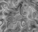
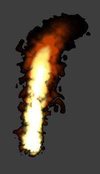
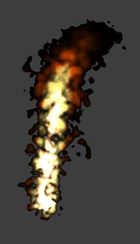
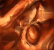
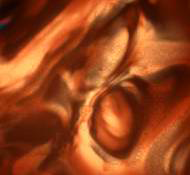
Sometimes it can help to use the Slices mode (see Preview), especially if you try to adjust the shape of the cloud. Try out the Slices mode using the images below as a guide.
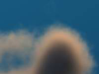
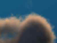
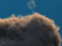
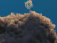
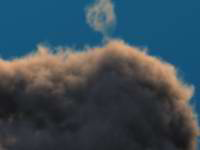
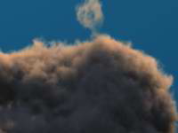
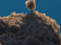
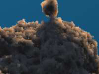
The following example is a slice through particles. A fractal was used for the Density Input shape of the particles. The first value of the fractal remains at 1, the second value was adjusted as shown in the following images.
Set up the lookup table as shown in this section.
For information on the lookup table parameters, see Lookup Table.
The lookup table is a low-resolution version of your volume object. It should cover the shape of the object, but does not require detail, which is added by the input textures.
If it does not cover the shape, then it can be that some parts of your volume are not ignored.
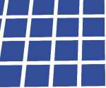
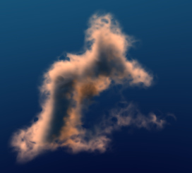
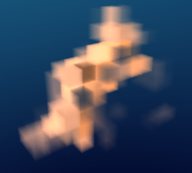
Enable the Preview Mode (see Preview), set the Lookup Table Reduce value to "---", and select the Render Lookup Table option.
Set the Cell Interpolation (see Lookup Table) to No Interpolation. This way you can clearly see the size of the cells.
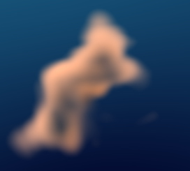
Then change the Cell Interpolation to Linear to see the result.
The lookup table holds the illumination/shadow information for the whole cloud. If you have small shadows, either from other thin objects casting shadows on the volume or from small details of the volume itself, then the illumination could flicker.
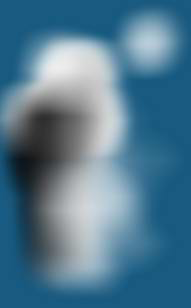
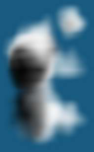
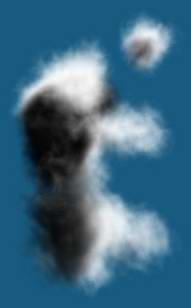
Now take a look at the images above. Image C was correct for the shape, but the shadow is very hard, the edge of the volume is crisp, and small details are already casting shadows.
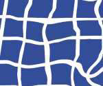
The small, separate particle at the top right is casting shadows on the main particle cluster, but in image C the shadow is almost gone and very blurred. It will definitely flicker. In this case, the cell size for the final render should be something between Images C and D.
As long as you can see the lines of the table (when you render the table only), it will probably flicker in your animation. Try using Cubic Interpolation, reduce the Cell Size, or use multiple samples per cell for illumination.
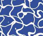
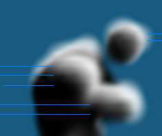
If you have medium-dense particles, you can sometimes see the lines of the lookup table, although the lookup table has enough resolution to catch all the shadow detail.
Take a look at the following image. If you follow the blue lines into the volume, you can see the lines inside the illumination of the cloud.
If you select Cubic Interpolation, the lines will disappear.
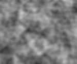
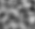
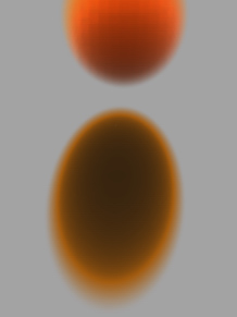
Usually, one sample is used to fill a cell with density, color, and illumination. However, if you have a very thin density texture, it's possible that this sample misses the texture. This results in cubic holes (see following image).
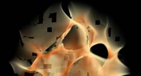
If you have a density texture with a very small and hard contrast, it's possible that a sample could hit a small white point on the texture, even though the average color in this area is gray. The result will be flickering in the alpha of the lookup table.
To eliminate this problem, you can use multiple samples per cell (deselect the Simple Mode option on the Marching page to display the parameters you need — see Marching).
The shader has a Memory Limit setting for the lookup table (see Lookup Table). Without this limit, you can easily reach a few GB of memory for this shader, which would lead to a render exit of mental ray.
An automatic reduction of the lookup table is not possible because it would lead to strange behavior of a sequence (such as the lookup table flickering from frame to frame).
If you reach the memory limit, the shader issues an warning message into the log file of how many MB the table would take.
Because you probably don't look into the log every time you render, or can't because it is a single frame in a farm-rendered sequence, the shader will reduce the lookup table to 20x20x20 and turns the volume red. The red volume is basically a warning that if the shader were to continue with the current settings, it would take all the memory.
Here are some steps to take to help you reduce the memory used:
Increase the Cell Size: This is the first step. Take a look at the Cell Size tips previously discussed. If it flickers, try to use multiple samples for each cell (Density and Illumination).
If you cannot reduce the cell size in all directions, try to reduce it in only one axis. For example, if the light is coming from the top, then you need more shadow detail in the top-bottom direction.
Animate the Cell Size: You have a close-up and need fine shadows, but you also see the total volume at a different frame? Just animate the Cell Size value.
Increase the Memory Limit value, which is set to 1250 MB by default.
Disable features: The lookup table takes a different amount of memory depending on the features you activate:
Reduce the particle volume size: Very often, you emit particles and they just fly through your whole scene until they die, even though you are just rendering some the particles. If you use an obstacle that kills the particles after they pass the camera, you can save a lot of memory (consider shadows and reflections from outside the view area).
Combine Auto Bounding Box with Manual Bounding Box: If many of the particles are not seen (such as if they are behind the camera), then you don't need to include the whole particle object in your rendering. You can restrict the Auto Bounding Box of your particle object with a Manual Bounding Box. For example, select Manual BBox and the User Camera Coordinates options, and limit the Min/Max Z bounding box size in the negative Z direction (behind camera).
Axis-aligned volume: The lookup table is axis-aligned. If your particle stream moves diagonally, you can waste a lot of cells on empty space. You could rotate the scene's world (camera, lights, emitter, forces) or rotate the particle object.
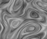
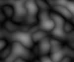
On rare occasions with high densities and a fine volume structure, the lookup table could be visible (see first image below).
To solve this problem, deselect the Simple Mode option on the Marching page.
Then increase the Max value for the Evaluate input textures only if volume density is between parameter.
|
|
 Except where otherwise noted, this work is licensed under a Creative Commons Attribution-NonCommercial-ShareAlike 3.0 Unported License